
Page 198 - Phase-Locked Loops Design, Simulation, and Applications
P. 198
MIXED-SIGNAL PLL APPLICATIONS PART 1: INTEGER-N FREQUENCY
SYNTHESIZERS Ronald E. Best 122
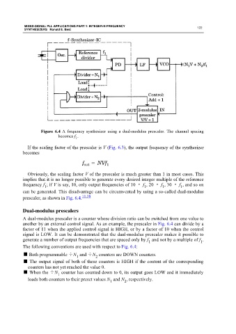
Figure 6.4 A frequency synthesizer using a dual-modulus prescaler. The channel spacing
becomes f .
1
If the scaling factor of the prescaler is V (Fig. 6.3), the output frequency of the synthesizer
becomes
Obviously, the scaling factor V of the prescaler is much greater than 1 in most cases. This
implies that it is no longer possible to generate every desired integer multiple of the reference
frequency f ; if V is say, 10, only output frequencies of 10 · f , 20 · f , 30 · f , and so on
1 1 1 1
can be generated. This disadvantage can be circumvented by using a so-called dual-modulus
prescaler, as shown in Fig. 6.4. 11,38
Dual-modulus prescalers
A dual-modulus prescaler is a counter whose division ratio can be switched from one value to
another by an external control signal. As an example, the prescaler in Fig. 6.4 can divide by a
factor of 11 when the applied control signal is HIGH, or by a factor of 10 when the control
signal is LOW. It can be demonstrated that the dual-modulus prescaler makes it possible to
generate a number of output frequencies that are spaced only by f and not by a multiple of f .
1
1
The following conventions are used with respect to Fig. 6.4:
■ Both programmable ÷N and ÷N counters are DOWN counters.
1 2
■ The output signal of both of these counters is HIGH if the content of the corresponding
counters has not yet reached the value 0.
■ When the ÷N counter has counted down to 0, its output goes LOW and it immediately
1
loads both counters to their preset values N and N , respectively.
1
2