
Page 251 - Phase-Locked Loops Design, Simulation, and Applications
P. 251
MIXED-SIGNAL PLL APPLICATIONS PART 1: INTEGER-N FREQUENCY
SYNTHESIZERS Ronald E. Best 149
We assumed hitherto that is constant over frequency, hence it has a white
spectrum. In reality, however, we must account for flicker noise, too. In analogy with Sec.
6.7.1 and Eq. (6.11), we can define the noise spectral density as
(6.31)
where is a constant and f is the corner frequency of flicker noise. For the phase
c
perturbation of the VCO output signal, we can therefore write
(6.32)
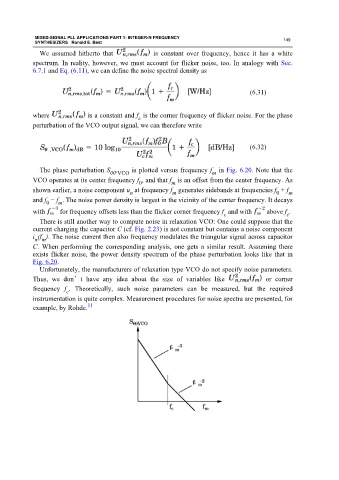
The phase perturbation S , is plotted versus frequency f in Fig. 6.20. Note that the
m
θθ VCO
VCO operates at its center frequency f , and that f is an offset from the center frequency. As
0 m
shown earlier, a noise component u at frequency f generates sidebands at frequencies f + f
n
0
m
m
and f − f . The noise power density is largest in the vicinity of the center frequency. It decays
0 m
with for frequency offsets less than the flicker corner frequency f and with above f .
c
c
There is still another way to compute noise in relaxation VCO: One could suppose that the
current charging the capacitor C (cf. Fig. 2.23) is not constant but contains a noise component
i (f ). The noise current then also frequency modulates the triangular signal across capacitor
n m
C. When performing the corresponding analysis, one gets a similar result. Assuming there
exists flicker noise, the power density spectrum of the phase perturbation looks like that in
Fig. 6.20.
Unfortunately, the manufacturers of relaxation type VCO do not specify noise parameters.
Thus, we don’t have any idea about the size of variables like or corner
frequency f . Theoretically, such noise parameters can be measured, but the required
c
instrumentation is quite complex. Measurement procedures for noise spectra are presented, for
11
example, by Rohde.