
Page 256 - Phase-Locked Loops Design, Simulation, and Applications
P. 256
MIXED-SIGNAL PLL APPLICATIONS PART 1: INTEGER-N FREQUENCY
SYNTHESIZERS Ronald E. Best 152
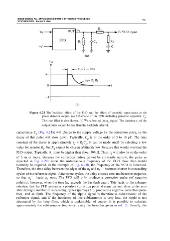
Figure 6.21 The backlash effect of the PFD and the effect of parasitic capacitance at the
phase detector output. (a) Schematic of the PFD including parasitic capacitor C .
p
The loop filter is also shown. (b) Waveform of the u signal. The duration τ of the
1
d
output pulse cannot be less than the backlash interval.
capacitance C (Fig. 6.21a) will charge to the supply voltage by the correction pulse, so the
p
decay of that pulse will slow down. Typically, C is in the order of 5 to 10 pF. The time
p
constant of the decay is approximately τ = R C . It can be made small by selecting a low
2
1 p
value for resistor R , but R cannot be chosen arbitrarily low, because this would overload the
1
1
PFD output. Typically, R must be higher than about 500 Ω. Thus, τ will also be on the order
1 2
of 5 ns or more. Because the correction pulses cannot be arbitrarily narrow, the pulse as
depicted in Fig. 6.21b alters the instantaneous frequency of the VCO more than would
normally be required. In the example of Fig. 6.21b, the frequency of the VCO is increased.
Therefore, the time delay between the edges of the u and u ′ becomes shorter in succeeding
2
1
cycles of the reference signal. After some cycles, the delay crosses zero and becomes negative,
so that u ′ leads u now. The PFD will only produce a correction pulse (of negative
2
1
polarity), however, when the time lag exceeds the backlash again. This leads to the unhappy
situation that the PFD generates a positive correction pulse at some instant, stays in the zero
state during a number of succeeding cycles (perhaps 10), produces a negative correction pulse
then, and so forth. The frequency of the ripple signal is therefore a subharmonic of the
reference signal, and if the frequency of this subharmonic is very low, the ripple is not
attenuated by the loop filter, which is undesirable, of course. It is possible to calculate
approximately the subharmonic frequency, using the formulas given in ref. 15. Usually, the