
Page 84 - Phase-Locked Loops Design, Simulation, and Applications
P. 84
MIXED-SIGNAL PLL ANALYSIS Ronald E. Best 59
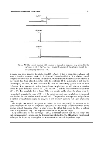
Figure 3.8 The weight function G(t) required to simulate a frequency step applied to the
reference input of the PLL. (ω = angular frequency of the reference signal; Δω =
1
frequency step applied at t = 0.)
a narrow and steep impulse, the stroke should be elastic. If this is done, the pendulum will
show a transient response, mostly in the form of damped oscillation. If a relatively small
weight is dropped onto the platform, the final deflection of the pendulum will be the same as if
the weight had been placed smoothly onto the platform. If the pendulum is not heavily
overdamped, however, its peak deflection will be considerably greater than its final
deflection. If we increase the weight dropped onto the platform, we will observe a situation
where the peak deflection exceeds 90°, but not 180°, and the final deflection is less than
90°. We thus conclude that a linear PLL can operate stably when the phase error θ
e
momentarily exceeds the value of 90°. If the weight dropped onto the platform is increased
ever further, the peak deflection will exceed 180°. The pendulum now tips over and performs
a number of revolutions around its axis, but it will probably come to rest again after some
time.
The weight that caused the system to unlock (at least temporarily) is observed to be
considerably smaller than the weight that represented the hold range. We therefore must define
another critical frequency offset—in other words, the offset that causes the PLL to unlock
when it is applied as a step. This frequency step is called the pull-out range.
Keep in mind that the pull-out range of a PLL is markedly smaller than its hold range. The
pull-out range may be considered the dynamic limit of stability. The PLL always stays locked
as long as the frequency steps applied to the system do not exceed the pull-out range.