
Page 87 - Phase-Locked Loops Design, Simulation, and Applications
P. 87
MIXED-SIGNAL PLL ANALYSIS Ronald E. Best 61
value. This implies that a PLL can become locked within one single-beat note between
reference frequency and output frequency, provided the frequency offset Δω is reduced below
a critical value called the lock range. This latter process is called the lock-in process. The
lock-in process is much faster than the pull-in process, but the lock range is smaller than the
pull-in range.
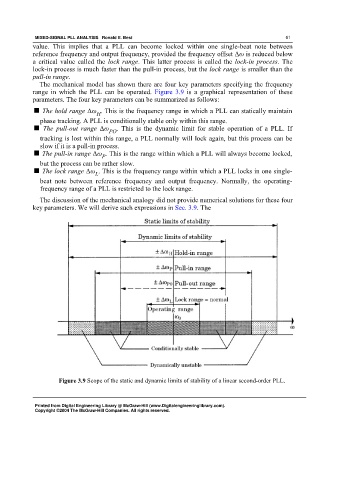
The mechanical model has shown there are four key parameters specifying the frequency
range in which the PLL can be operated. Figure 3.9 is a graphical representation of these
parameters. The four key parameters can be summarized as follows:
■ The hold range Δω . This is the frequency range in which a PLL can statically maintain
H
phase tracking. A PLL is conditionally stable only within this range.
■ The pull-out range Δω . This is the dynamic limit for stable operation of a PLL. If
PO
tracking is lost within this range, a PLL normally will lock again, but this process can be
slow if it is a pull-in process.
■ The pull-in range Δω . This is the range within which a PLL will always become locked,
P
but the process can be rather slow.
■ The lock range Δω . This is the frequency range within which a PLL locks in one single-
L
beat note between reference frequency and output frequency. Normally, the operating-
frequency range of a PLL is restricted to the lock range.
The discussion of the mechanical analogy did not provide numerical solutions for these four
key parameters. We will derive such expressions in Sec. 3.9. The
Figure 3.9 Scope of the static and dynamic limits of stability of a linear second-order PLL.
Printed from Digital Engineering Library @ McGraw-Hill (www.Digitalengineeringlibrary.com).
Copyright ©2004 The McGraw-Hill Companies. All rights reserved.