
Page 10 - Photodetection and Measurement - Maximizing Performance in Optical Systems
P. 10
Photodetection Basics
Photodetection Basics 3
Space- Electric
Photon charge field
density
A
p
V
Depletion Region
n
Field-driven
K
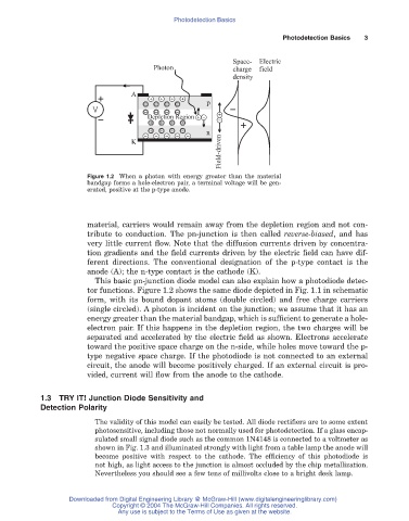
Figure 1.2 When a photon with energy greater than the material
bandgap forms a hole-electron pair, a terminal voltage will be gen-
erated, positive at the p-type anode.
material, carriers would remain away from the depletion region and not con-
tribute to conduction. The pn-junction is then called reverse-biased, and has
very little current flow. Note that the diffusion currents driven by concentra-
tion gradients and the field currents driven by the electric field can have dif-
ferent directions. The conventional designation of the p-type contact is the
anode (A); the n-type contact is the cathode (K).
This basic pn-junction diode model can also explain how a photodiode detec-
tor functions. Figure 1.2 shows the same diode depicted in Fig. 1.1 in schematic
form, with its bound dopant atoms (double circled) and free charge carriers
(single circled). A photon is incident on the junction; we assume that it has an
energy greater than the material bandgap, which is sufficient to generate a hole-
electron pair. If this happens in the depletion region, the two charges will be
separated and accelerated by the electric field as shown. Electrons accelerate
toward the positive space charge on the n-side, while holes move toward the p-
type negative space charge. If the photodiode is not connected to an external
circuit, the anode will become positively charged. If an external circuit is pro-
vided, current will flow from the anode to the cathode.
1.3 TRY IT! Junction Diode Sensitivity and
Detection Polarity
The validity of this model can easily be tested. All diode rectifiers are to some extent
photosensitive, including those not normally used for photodetection. If a glass encap-
sulated small signal diode such as the common 1N4148 is connected to a voltmeter as
shown in Fig. 1.3 and illuminated strongly with light from a table lamp the anode will
become positive with respect to the cathode. The efficiency of this photodiode is
not high, as light access to the junction is almost occluded by the chip metallization.
Nevertheless you should see a few tens of millivolts close to a bright desk lamp.
Downloaded from Digital Engineering Library @ McGraw-Hill (www.digitalengineeringlibrary.com)
Copyright © 2004 The McGraw-Hill Companies. All rights reserved.
Any use is subject to the Terms of Use as given at the website.