
Page 132 - Photodetection and Measurement - Maximizing Performance in Optical Systems
P. 132
Useful Electronic Circuits and Construction Techniques to Get You Going
Useful Electronic Circuits and Construction Techniques to Get You Going 125
works as well as a high voltage and a high resistor. However, the higher the
voltage, the more like a pure current source it looks and the more stable will
be the current with temperature variations in the LED. In Fig. 6.2a the current
I = (V b - V f)/R. Unfortunately, the diode voltage V f is also a function of current,
but not much of one, just logarithmic. Hence a reasonable approach, since you
probably don’t know the details of the IV characteristic of the cheap LED, is to
take any available 5V or 12V DC supply or battery, assume a forward LED
voltage of 1.5V, an operating current of 10mA and calculate the load resistor.
Power it up, measure the LED voltage, and adjust the resistor if necessary. It’s
unlikely that you will be far wrong. If the LED is more costly or you don’t have
a replacement, you might start with a ten times larger resistor or wind up the
supply voltage slowly, monitoring the current until you are sure of the polarity,
the characteristics, and hence the necessary design.
Connecting to a laboratory signal generator to modulate the LED is hardly
any more complex (Fig. 6.2b). Use the peak generator voltage instead of V b in
your calculations and proceed as above. Unless the LED has a metal can which
you would like to ground, you might want to swap the positions of LED and
load resistor as shown. This makes it easier to monitor the LED current via the
voltage on the load using a grounded oscilloscope. If the generator is bipolar,
one half-cycle could take the LED into breakdown. If you suspect this, limit the
(a) (b) (c)
±5V
R (560) LED
±5V C 1k
V b Si
(12V) I (18.6mA) R (180) 330R V b
V (1.6V) (12V)
f
12V 12V
(d) (e) (f) (g)
Red 100R 5–30V V+
LED 470 470
2N2906 Rset
V b 6.8R 2.2k G D
(9V) V-
S
10k 10k
820R LED LM334
(bottom view) 2N2222 VN2222
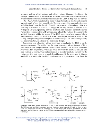
Figure 6.2 LED drive circuit fragments. As the LED is a diode, it is more comfortable to define
the LED current and let the voltage take on whatever value it needs. (b) and (c) show square
wave and sine wave modulation schemes. (d), (e) are simple DC current generators. If more
current is needed than an opamp or CMOS logic gate can supply, use a bipolar transistor or FET
buffer (f,g).
Downloaded from Digital Engineering Library @ McGraw-Hill (www.digitalengineeringlibrary.com)
Copyright © 2004 The McGraw-Hill Companies. All rights reserved.
Any use is subject to the Terms of Use as given at the website.