
Page 135 - Photodetection and Measurement - Maximizing Performance in Optical Systems
P. 135
Useful Electronic Circuits and Construction Techniques to Get You Going
128 Chapter Six
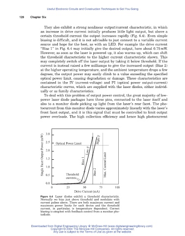
They also exhibit a strong nonlinear output/current characteristic, in which
an increase in drive current initially produces little light output, but above a
certain threshold current the output increases rapidly (Fig. 6.4). Even simple
biasing is difficult, and it is not advisable to just connect to a variable current
source and hope for the best, as with an LED. For example the drive current
“Bias 1” in Fig. 6.4 may initially give the desired output, here about 0.75mW.
However, as soon as the laser is powered up, it also warms up, which can shift
the threshold characteristic to the higher current characteristic shown. This
may completely switch off the laser output by taking it below threshold. If the
current is instead raised a few milliamps to give the increased output (Bias 2)
at the higher operating temperature, and the ambient temperature drops a few
degrees, the output power may easily climb to a value exceeding the specified
optical power limit, causing degradation or damage. These characteristics are
contained in the IV (current-voltage) and PI (optical power output-current)
characteristic curves, which are supplied with the laser diodes, either individ-
ually or as family characteristics.
To deal with this problem of output power control, the great majority of low-
power laser diode packages have three pins, connected to the laser itself and
also to a monitor diode picking up light from the laser’s rear facet. The pho-
tocurrent from this monitor diode varies approximately linearly with the laser’s
front facet output, and it is this signal that must be controlled to limit output
power overloads. The high collection efficiency and hence high photocurrent
3.0
Single Facet Output Power (mW) 2.5 Optical Power Limit Bias 1 Low-T High-T Max. Current Limit
2.0
1.5
1.0
Threshold
0.5
currents Bias 2
0.0
0 25 50 75 100
Drive Current (mA)
Figure 6.4 Laser diodes exhibit a threshold characteristic.
Normally we bias just above threshold and modulate with
current pulses above. There are both maximum current and
maximum power limits for each device and the threshold
current, in particular, is temperature dependent. Correct
biasing is simplest with feedback control from a monitor pho-
todiode.
Downloaded from Digital Engineering Library @ McGraw-Hill (www.digitalengineeringlibrary.com)
Copyright © 2004 The McGraw-Hill Companies. All rights reserved.
Any use is subject to the Terms of Use as given at the website.