
Page 138 - Photodetection and Measurement - Maximizing Performance in Optical Systems
P. 138
Useful Electronic Circuits and Construction Techniques to Get You Going
Useful Electronic Circuits and Construction Techniques to Get You Going 131
high intensity measurement precision with a diode laser source, more care will
be needed. Instead of using the laser’s rear facet detector for stabilization, you
could use the front facet output, for example using a small beam-splitter, and
thereby remove one source of error. In practice it is easier to use the internal
rear-facet detector for rough intensity stabilization, with an external precision
detector for referencing. Note too that the laser stabilization circuits are just
as applicable to light emitting diodes, given an independent detector. Tech-
niques for power stabilization and referencing are described in Chap. 8.
6.6 Modulation Oscillators
In the great majority of optical measurement systems the light source will be
modulated, and for LED-sourced systems the basic requirements are, well,
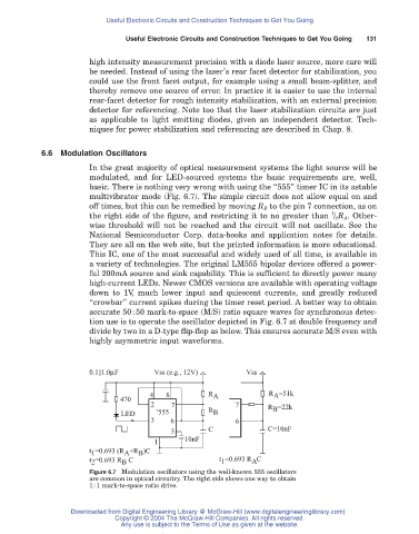
basic. There is nothing very wrong with using the “555” timer IC in its astable
multivibrator mode (Fig. 6.7). The simple circuit does not allow equal on and
off times, but this can be remedied by moving R B to the pin 7 connection, as on
1
the right side of the figure, and restricting it to no greater than / 2 R A. Other-
wise threshold will not be reached and the circuit will not oscillate. See the
National Semiconductor Corp. data-books and application notes for details.
They are all on the web site, but the printed information is more educational.
This IC, one of the most successful and widely used of all time, is available in
a variety of technologies. The original LM555 bipolar devices offered a power-
ful 200mA source and sink capability. This is sufficient to directly power many
high-current LEDs. Newer CMOS versions are available with operating voltage
down to 1V, much lower input and quiescent currents, and greatly reduced
“crowbar” current spikes during the timer reset period. A better way to obtain
accurate 50:50 mark-to-space (M/S) ratio square waves for synchronous detec-
tion use is to operate the oscillator depicted in Fig. 6.7 at double frequency and
divide by two in a D-type flip-flop as below. This ensures accurate M/S even with
highly asymmetric input waveforms.
0.1||1.0μF Vss (e.g., 12V) Vss
4 8 R A R =51k
A
470
2 7 7 R =22k
LED '555 R B B
3 6 6
5 C C=10nF
10nF
1
t =0.693 (R +R )C
B
A
1
t =0.693 R C t =0.693 R C
A
1
2
B
Figure 6.7 Modulation oscillators using the well-known 555 oscillators
are common in optical circuitry. The right side shows one way to obtain
1:1 mark-to-space ratio drive.
Downloaded from Digital Engineering Library @ McGraw-Hill (www.digitalengineeringlibrary.com)
Copyright © 2004 The McGraw-Hill Companies. All rights reserved.
Any use is subject to the Terms of Use as given at the website.