
Page 141 - Photodetection and Measurement - Maximizing Performance in Optical Systems
P. 141
Useful Electronic Circuits and Construction Techniques to Get You Going
134 Chapter Six
CD4069UB HC4040
CLK
4096 Vcc
64 2048
R =1M 32 1024
f
R d 128 256
16 512
X-Reson.
8 RST
C 1 C 2 4 CLK
In
GND 2
HC4024 HC4020
4096 Vcc
In
CLK Vcc 8192 2048
RST NC 16384 1024
128 2 64 256
64 4 32 512
32 NC 128 RST
16 8 16 CLK
In
GND NC GND 2
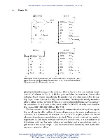
Figure 6.10 Ceramic resonators are best excited using “unbuffered” logic
gates. You may need to tweak the capacitors to get it to oscillate reliably.
Alternative divider ICs are also shown.
piezomechanical resonators to oscillate. This is down to the two loading capac-
itors C 1 , C 2 shown in Fig. 6.10. With a good model of the resonator, they can be
calculated and chosen analytically. In practice we are often reduced to tweak-
ing to get them to work. Luckily, once tweaked, the design is usually transfer-
able to other similar devices. Division of the fundamental frequency can simply
be carried out in a divider chain, such as the 74HC4060 already mentioned or
the related HC4020, HC4024, or HC4040.
Neither ceramic oscillators used for radio intermediate frequency filtering nor
the watch crystal offer sufficient choice of frequencies for some applications. In
this case, it is convenient to move to the 1 to 10MHz region, where the choice
of conventional quartz crystals is at its best. With correct choice of the loading
capacitors, all the above circuits can be used. The HC4060 is a nice solution as
it includes both the free gate to build an oscillator and a long divider chain to
get down to the audio range. If you need even more flexibility, look at the fre-
quency synthesizer chips.
Downloaded from Digital Engineering Library @ McGraw-Hill (www.digitalengineeringlibrary.com)
Copyright © 2004 The McGraw-Hill Companies. All rights reserved.
Any use is subject to the Terms of Use as given at the website.