
Page 144 - Photodetection and Measurement - Maximizing Performance in Optical Systems
P. 144
Useful Electronic Circuits and Construction Techniques to Get You Going
Useful Electronic Circuits and Construction Techniques to Get You Going 137
year-old pair of high quality Sennheiser stereo headphones. These have an impedance
of 2kW each, so in series they work very well. Listen close-up to a few modulated
optical sources: the PC monitor, TV screen, TV remote control, fluorescent room
lights, or your 8kHz crystal oscillator and LED driver. You should have no difficulty
hearing them all. Desktop 100/120Hz room lighting is a bit faint, but that is more a
limitation of your hearing’s low-frequency sensitivity, not the detector’s. Reverse
biasing the photodiode with a small battery improves performance, although that’s
getting a bit complicated!
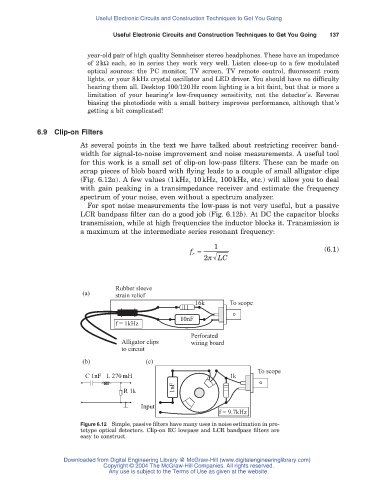
6.9 Clip-on Filters
At several points in the text we have talked about restricting receiver band-
width for signal-to-noise improvement and noise measurements. A useful tool
for this work is a small set of clip-on low-pass filters. These can be made on
scrap pieces of blob board with flying leads to a couple of small alligator clips
(Fig. 6.12a). A few values (1kHz, 10kHz, 100kHz, etc.) will allow you to deal
with gain peaking in a transimpedance receiver and estimate the frequency
spectrum of your noise, even without a spectrum analyzer.
For spot noise measurements the low-pass is not very useful, but a passive
LCR bandpass filter can do a good job (Fig. 6.12b). At DC the capacitor blocks
transmission, while at high frequencies the inductor blocks it. Transmission is
a maximum at the intermediate series resonant frequency:
1
f r = (6.1)
2p LC
Rubber sleeve
(a) strain relief
16k To scope
10nF
f = 1kHz
Perforated
Alligator clips wiring board
to circuit
(b) (c)
To scope
C 1nF L 270 mH 1k
1nF
R 1k
Input
f = 9.7kHz
Figure 6.12 Simple, passive filters have many uses in noise estimation in pro-
totype optical detectors. Clip-on RC lowpass and LCR bandpass filters are
easy to construct.
Downloaded from Digital Engineering Library @ McGraw-Hill (www.digitalengineeringlibrary.com)
Copyright © 2004 The McGraw-Hill Companies. All rights reserved.
Any use is subject to the Terms of Use as given at the website.