Page 149 - Photodetection and Measurement - Maximizing Performance in Optical Systems
P. 149

Control of Ambient Light

            142   Chapter Seven

                        Ambient light
                                                              C f
                                                               R
                                      ~mW                       f
                                                    I p
                                    1nW                    -
                                                      C p  +
                             LED
                             source
                                      ~mW
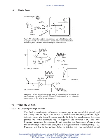
                        Figure 7.1 Many laboratory experiments are bathed in interfer-
                        ing light, which can sometimes be much more intense than the
                        desired signal. The first defence weapon is modulation.


                        V                 Time
                         b       I p
                                              +             Time
                                        C     - A
                                                            p L
                                R L  R 1               V o = I  R
                                1M   100M
                                                           20dB/dec
                        (a) Voltage Follower            V o


                                                                 f c
                                                Time
                                     R  1M                 120Hz    Frequency
                                       L
                                                  V o = I  R
                                                       p L
                               I p    + A
                                      -
                        (b) Transimpedance
                                                             Time
                        Figure 7.2 AC coupling is not much help to reduce the DC response, as
                        the front end can still overload. Choose f c high enough to get adequate
                        suppression at the interfering frequency.


            7.2 Frequency Domain
            7.2.1 AC Coupling: voltage follower
                        The first characteristic difference between our weak modulated signal and
                        the strong ambient light is of course its modulation frequency; ambient light
                        intensity generally doesn’t change rapidly. To help the synchronous detection
                        process we could therefore try to suppress the receiver’s DC and low-
                        frequency response, for example by AC coupling the first stage. Where a bias
                        box and voltage follower are used, this is straightforward to arrange (Fig. 7.2).
                        Photocurrent due to the incident light, containing both our modulated signal


                   Downloaded from Digital Engineering Library @ McGraw-Hill (www.digitalengineeringlibrary.com)
                              Copyright © 2004 The McGraw-Hill Companies. All rights reserved.
                               Any use is subject to the Terms of Use as given at the website.
   144   145   146   147   148   149   150   151   152   153   154