
Page 152 - Photodetection and Measurement - Maximizing Performance in Optical Systems
P. 152
Control of Ambient Light
Control of Ambient Light 145
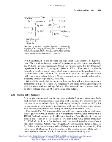
+V bias
BPW34
I p Output (+ve) 1k5 C 33nF
L
R 330k ZTX
L
L
ZTX384 214 R 330k
C 33nF I p Output (-ve)
L
1k5
BPW34
-V bias
Equivalent Load:
Low f: << R L
High f: R L
Figure 7.4 A nonlinear transistor load can synthesize the
operation of an inductor, with excellent suppression of DC
and low-frequency light. Low frequency photocurrents
forward bias the transistor and short out the load resistor.
Circuit reproduced by permission of Zetex Ltd.
from being turned on and allowing the high-value load resistor to be fully uti-
lized. The transition between low- and high-frequency behavior occurs when R L
and C L have the same impedance. Using the values shown, the low-frequency
impedance is about 1kW, rising to 250kW at 50kHz. The circuit is a simple
example of an electronic gyrator, which uses a capacitor and gain stage to syn-
thesize a large value inductor. The output must be taken to a high-impedance
buffer such as a voltage follower. Negative output voltages can be achieved by
switching transistor polarities, as shown.
With a little manipulation the active load can be used in a transimpedance
configuration (Fig. 7.5) to give DC suppression and speed advantages compared
with the same load and voltage follower. This network does, however, lead to
an offset voltage of about 0.8V at the amplifier output.
7.2.5 General active feedback
In principle, any network can be used to provide the frequency-dependent feed-
back around a transimpedance amplifier that is required to suppress the DC
response to static ambient light. By exchanging the single transistor of Fig. 7.5
for an opamp we can improve performance and ease the design compromises.
This alternative approach has been published by Burr-Brown (1993).
The circuit (Fig. 7.6) is designed for use with the transimpedance configura-
tion of photoreceiver. It consists of a conventional receiver, here drawn with a
100MW feedback resistor, with additional feedback from the circuitry in the
shaded box. This is a essentially a low-pass filter with cutoff frequency
f c = 1/2pR 1C 1. As it is in the feedback path, the overall transimpedance has a
high-pass response. Well above f c = R L/2pR 1C 1R 3 the transimpedance is equal to
R L. Below f c the response drops off as if there were an inductor across R L. The
extra factor R L/R 3 comes from the ability of the smaller resistor R 3 to deliver
more feedback current than R L itself, which increases the loop gain.
Downloaded from Digital Engineering Library @ McGraw-Hill (www.digitalengineeringlibrary.com)
Copyright © 2004 The McGraw-Hill Companies. All rights reserved.
Any use is subject to the Terms of Use as given at the website.