
Page 153 - Photodetection and Measurement - Maximizing Performance in Optical Systems
P. 153
Control of Ambient Light
146 Chapter Seven
2N2907A
DC +
Modulation
R 330 k C Time
10nF
I -
BPW34 p
V o = I R
p L
+
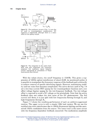
Figure 7.5 The nonlinear circuit of Fig. 7.4 can also
be used in transimpedance configuration. DC
response is suppressed, although there is a static
offset at the opamp output.
C2 4n7 R2
OP177
220k
-
R3 + C1 4n7
10M R1
220k
R 100M
L
V = I R
p L
o
I -
BPX65 p +
OPA121
Figure 7.6 The integrator in the active feed-
back loop also suppresses low frequency
response, but maintains signal linearity.
Circuit reproduced by permission of Texas
Instruments Burr-Brown.
With the values shown, the cutoff frequency is 1539Hz. This gives a sup-
pression of 120Hz optical interference of about 25dB. As mentioned earlier, it
is possible to manipulate the frequency response of the feedback path arbitrarily
to achieve removal of specific interfering signals. However, maintaining stabil-
ity and low noise then becomes complicated. The active devices used in Fig. 7.6
are a low-bias current FET opamp for the transimpedance function and a low
offset voltage bipolar opamp for the low-frequency feedback. The low-voltage
offset is required to avoid a DC voltage on the photodiode. Note that the active
feedback does not reduce the shot noise of the DC photocurrent. The full
current still flows; it is just split with low frequencies flowing through R 3 and
high frequencies through R L.
Figure 7.7 shows the resulting performance of such an ambient-suppressed
receiver. The upper curve is with a simple 1MW load resistor. We can see the
rectified sine-wave interference due to 100Hz fluorescent lighting and the unre-
solved 10kHz modulation from the source. The lower trace is the same circuit
with the frequency-dependent feedback connected. The modulation amplitude
Downloaded from Digital Engineering Library @ McGraw-Hill (www.digitalengineeringlibrary.com)
Copyright © 2004 The McGraw-Hill Companies. All rights reserved.
Any use is subject to the Terms of Use as given at the website.