
Page 151 - Photodetection and Measurement - Maximizing Performance in Optical Systems
P. 151
Control of Ambient Light
144 Chapter Seven
V b I Time
p
+ Time
C L R L - A V o = I R
p L
1M
(a) Voltage Follower
DC +
Modulation L
R L Time
1M
I p - V o = I R
p L
+
(b) Transimpedance
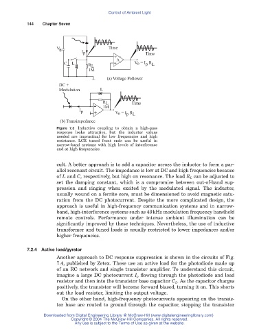
Figure 7.3 Inductive coupling to obtain a high-pass
response looks attractive, but the inductor values
needed are impractical for low frequencies and high
resistance. LCR tuned front ends can be useful in
narrow-band systems with high levels of interference
and at high frequencies.
cult. A better approach is to add a capacitor across the inductor to form a par-
allel resonant circuit. The impedance is low at DC and high frequencies because
of L and C, respectively, but high on resonance. The load R L can be adjusted to
set the damping constant, which is a compromise between out-of-band sup-
pression and ringing when excited by the modulated signal. The inductor,
usually wound on a ferrite core, must be dimensioned to avoid magnetic satu-
ration from the DC photocurrent. Despite the more complicated design, the
approach is useful in high-frequency communication systems and in narrow-
band, high-interference systems such as 40kHz modulation frequency handheld
remote controls. Performance under intense ambient illumination can be
significantly improved by these techniques. Nevertheless, the use of inductive
transformer and tuned loads is usually restricted to lower impedances and/or
higher frequencies.
7.2.4 Active load/gyrator
Another approach to DC response suppression is shown in the circuits of Fig.
7.4, published by Zetex. These use an active load for the photodiode made up
of an RC network and single transistor amplifier. To understand this circuit,
imagine a large DC photocurrent I p flowing through the photodiode and load
resistor and then into the transistor base capacitor C L. As the capacitor charges
positively, the transistor will become forward biased, turning it on. This shorts
out the load resistor, limiting the output voltage.
On the other hand, high-frequency photocurrents appearing on the transis-
tor base are routed to ground through the capacitor, stopping the transistor
Downloaded from Digital Engineering Library @ McGraw-Hill (www.digitalengineeringlibrary.com)
Copyright © 2004 The McGraw-Hill Companies. All rights reserved.
Any use is subject to the Terms of Use as given at the website.