
Page 142 - Photodetection and Measurement - Maximizing Performance in Optical Systems
P. 142
Useful Electronic Circuits and Construction Techniques to Get You Going
Useful Electronic Circuits and Construction Techniques to Get You Going 135
Second only to the bias box in its continuous usefulness around the lab is a
modulated LED source. The crystal-controlled audio-frequency transmitter
(Fig. 6.8a) with a 3.6V lithium battery is about right for finding out whether
your receiver has just died, checking the continuity of a fiber link, or testing
the rise time of a new high-sensitivity detector circuit. The circuit is compact
enough to be built into a flashlight housing or small diecast box. My recom-
mendation is to make several and always keep a few hidden away, as they
have a high diffusion coefficient! A good runner-up for testing receivers is
a handheld IR remote control. As every TV, video, stereo, gas-fire, and air-
conditioning system these days seems to have a remote control and they last
longer than the equipment itself, there are usually surplus units available. The
wavelength is typically 880nm or 940nm, although changing the LED for a dif-
ferent wavelength is not difficult. The slow code transmission can make scope
triggering difficult.
6.7 Single Supply Receivers
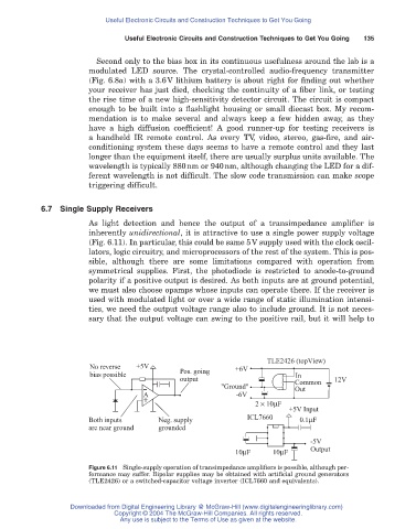
As light detection and hence the output of a transimpedance amplifier is
inherently unidirectional, it is attractive to use a single power supply voltage
(Fig. 6.11). In particular, this could be same 5V supply used with the clock oscil-
lators, logic circuitry, and microprocessors of the rest of the system. This is pos-
sible, although there are some limitations compared with operation from
symmetrical supplies. First, the photodiode is restricted to anode-to-ground
polarity if a positive output is desired. As both inputs are at ground potential,
we must also choose opamps whose inputs can operate there. If the receiver is
used with modulated light or over a wide range of static illumination intensi-
ties, we need the output voltage range also to include ground. It is not neces-
sary that the output voltage can swing to the positive rail, but it will help to
TLE2426 (topView)
No reverse +5V +6V
bias possible Pos. going In
output Common 12V
"Ground" Out
+ A -6V
-
2 ¥ 10μF
+5V Input
Both inputs Neg. supply ICL7660 0.1μF
are near ground grounded
-5V
Output
10μF 10μF
Figure 6.11 Single-supply operation of transimpedance amplifiers is possible, although per-
formance may suffer. Bipolar supplies may be obtained with artificial ground generators
(TLE2426) or a switched-capacitor voltage inverter (ICL7660 and equivalents).
Downloaded from Digital Engineering Library @ McGraw-Hill (www.digitalengineeringlibrary.com)
Copyright © 2004 The McGraw-Hill Companies. All rights reserved.
Any use is subject to the Terms of Use as given at the website.