
Page 136 - Photodetection and Measurement - Maximizing Performance in Optical Systems
P. 136
Useful Electronic Circuits and Construction Techniques to Get You Going
Useful Electronic Circuits and Construction Techniques to Get You Going 129
detected means that sensitivity is not a problem (typically it is 100mA or more).
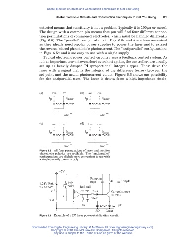
The design with a common pin means that you will find four different connec-
tion permutations of commoned electrodes, which must be handled differently
(Fig. 6.5). The “parallel” configurations in Figs. 6.5c and d are less convenient
as they ideally need bipolar power supplies to power the laser and to extract
the reverse-biased photodiode’s photocurrent. The “antiparallel” configurations
in Figs. 6.5a and b are easy to use with a single supply.
Typical electronic power control circuitry uses a feedback control system. As
it is so important to avoid even short overshoot spikes, the controllers are usually
set up as heavily damped PI (proportional, integral) types. These drive the
laser with a signal that is the integral of the difference (error) between the
set point and the actual photocurrent values. Figure 6.6 shows one possibility
for the antiparallel form. The laser is driven from a high-impedance single-
(a) +ve +ve (b) -ve -ve
I p I laser I p I laser
Gnd Gnd
(c) -ve +ve (d) +ve -ve
I p I laser I p I laser
Gnd Gnd
Figure 6.5 All four permutations of laser and monitor
photodiode polarity are available. The “antiparallel”
configurations are slightly more convenient to use with
a single-polarity power supply.
+5V
Damping
1.24V Ref. Set- 10μF 47 100μF
ZRA124Y point Rail-rail
V + + opamp 2.2k Current source
V - - 2N2905
3.9k 100nF
I p 10k 1μF
PD Laser
Figure 6.6 Example of a DC laser power-stabilization circuit.
Downloaded from Digital Engineering Library @ McGraw-Hill (www.digitalengineeringlibrary.com)
Copyright © 2004 The McGraw-Hill Companies. All rights reserved.
Any use is subject to the Terms of Use as given at the website.