Page 181 - Photodetection and Measurement - Maximizing Performance in Optical Systems
P. 181

Stability and Tempco Issues

            174   Chapter Eight

                                                             R L1
                            Current
                            control    Beam-
                                       splitter            -       Signal
                                                           +A
                                LED
                                                        PD1
                                             Cuvette
                        Monitor     -
                                    +A
                                          PD2
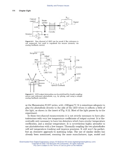
                        Figure 8.11 One channel of ADC can be saved if the reference is
                        not measured, but used to regulated the source intensity via
                        analog feedback control.


                                      R1
                            Set-point
                                      10k
                                         100nF
                                PD2        100k       IC2  1N4148     330
                                S1337
                                         2   7        AD711
                                                      3   7
                                         3    6        +    6
                                          -
                                             4                 1.5k  ZTX551
                                          +
                                         IC1          2  - 4
                                         LMC7101
                                                         22k          LED
                                                  1k
                                                                      -12V
                        LED
                                                                      DC
                                   PD2         Optical feedback


                        Figure 8.12 LED output intensities can be stabilized by closely coupling
                        source and reference photodiode, e.g., by gluing, and using a simple
                        analog feedback controller.

                        as the Hamamatsu S1337 series, with <100ppm/°C. It is sometimes adequate to
                        glue the photodiode directly to the side of the LED where it collects a little of
                        the light, as shown in the insert of Fig. 8.12. Most of the light passes by to the
                        experiment.
                          In these two-channel measurements it is not strictly necessary to have pho-
                        todetectors with very low temperature coefficients of output current. It is the-
                        oretically only necessary to have two detectors which have similar temperature
                        coefficients, and a similar temperature. It is nevertheless highly advisable to
                        use photodetectors with a low tempco. Thermally coupling the two photodiodes
                        will aid temperature tracking and improve precision. It still won’t be perfect,
                        but an obsessive approach to matching helps. The use of similar diodes has
                        already been mentioned, meaning the same manufacturer, type, model and


                   Downloaded from Digital Engineering Library @ McGraw-Hill (www.digitalengineeringlibrary.com)
                              Copyright © 2004 The McGraw-Hill Companies. All rights reserved.
                               Any use is subject to the Terms of Use as given at the website.
   176   177   178   179   180   181   182   183   184   185   186