
Page 180 - Photodetection and Measurement - Maximizing Performance in Optical Systems
P. 180
Stability and Tempco Issues
Stability and Tempco Issues 173
R L1
Beam-
splitter - Signal
+A
PD1
LED R L2
Source Cuvette
Ref.
-
+A
PD2
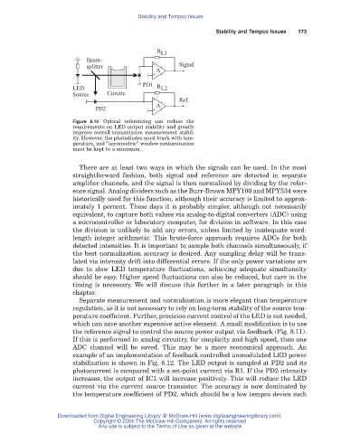
Figure 8.10 Optical referencing can reduce the
requirements on LED output stability and greatly
improve overall transmission measurement stabil-
ity. However, the photodiodes must track with tem-
perature, and “asymmetric” window contamination
must be kept to a minimum.
There are at least two ways in which the signals can be used. In the most
straightforward fashion, both signal and reference are detected in separate
amplifier channels, and the signal is then normalized by dividing by the refer-
ence signal. Analog dividers such as the Burr-Brown MPY100 and MPY534 were
historically used for this function, although their accuracy is limited to approx-
imately 1 percent. These days it is probably simpler, although not necessarily
equivalent, to capture both values via analog-to-digital converters (ADC) using
a microcontroller or laboratory computer, for division in software. In this case
the division is unlikely to add any errors, unless limited by inadequate word-
length integer arithmetic. This brute-force approach requires ADCs for both
detected intensities. It is important to sample both channels simultaneously, if
the best normalization accuracy is desired. Any sampling delay will be trans-
lated via intensity drift into differential errors. If the only power variations are
due to slow LED temperature fluctuations, achieving adequate simultaneity
should be easy. Higher speed fluctuations can also be reduced, but care in the
timing is necessary. We will discuss this further in a later paragraph in this
chapter.
Separate measurement and normalization is more elegant than temperature
regulation, as it is not necessary to rely on long-term stability of the source tem-
perature coefficient. Further, precision current control of the LED is not needed,
which can save another expensive active element. A small modification is to use
the reference signal to control the source power output via feedback (Fig. 8.11).
If this is performed in analog circuitry, for simplicity and high speed, then one
ADC channel will be saved. This may be a more economical approach. An
example of an implementation of feedback controlled unmodulated LED power
stabilization is shown in Fig. 8.12. The LED output is sampled at PD2 and its
photocurrent is compared with a set-point current via R1. If the PD2 intensity
increases, the output of IC1 will increase positively. This will reduce the LED
current via the current source transistor. The accuracy is now dominated by
the temperature coefficient of PD2, which should be a low tempco device such
Downloaded from Digital Engineering Library @ McGraw-Hill (www.digitalengineeringlibrary.com)
Copyright © 2004 The McGraw-Hill Companies. All rights reserved.
Any use is subject to the Terms of Use as given at the website.