
Page 179 - Photodetection and Measurement - Maximizing Performance in Optical Systems
P. 179
Stability and Tempco Issues
172 Chapter Eight
PIC or
10k C BASIC Stamp
220R
I/O pin 1 (drive Rt)
220R
I/O pin 2 (measure Rt)
ZTX550
Thermistor
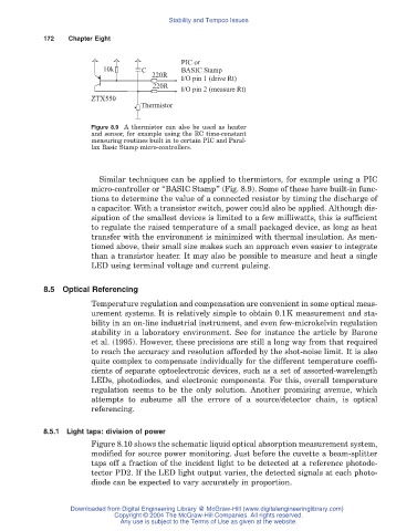
Figure 8.9 A thermistor can also be used as heater
and sensor, for example using the RC time-constant
measuring routines built in to certain PIC and Paral-
lax Basic Stamp micro-controllers.
Similar techniques can be applied to thermistors, for example using a PIC
micro-controller or “BASIC Stamp” (Fig. 8.9). Some of these have built-in func-
tions to determine the value of a connected resistor by timing the discharge of
a capacitor. With a transistor switch, power could also be applied. Although dis-
sipation of the smallest devices is limited to a few milliwatts, this is sufficient
to regulate the raised temperature of a small packaged device, as long as heat
transfer with the environment is minimized with thermal insulation. As men-
tioned above, their small size makes such an approach even easier to integrate
than a transistor heater. It may also be possible to measure and heat a single
LED using terminal voltage and current pulsing.
8.5 Optical Referencing
Temperature regulation and compensation are convenient in some optical meas-
urement systems. It is relatively simple to obtain 0.1K measurement and sta-
bility in an on-line industrial instrument, and even few-microkelvin regulation
stability in a laboratory environment. See for instance the article by Barone
et al. (1995). However, these precisions are still a long way from that required
to reach the accuracy and resolution afforded by the shot-noise limit. It is also
quite complex to compensate individually for the different temperature coeffi-
cients of separate optoelectronic devices, such as a set of assorted-wavelength
LEDs, photodiodes, and electronic components. For this, overall temperature
regulation seems to be the only solution. Another promising avenue, which
attempts to subsume all the errors of a source/detector chain, is optical
referencing.
8.5.1 Light taps: division of power
Figure 8.10 shows the schematic liquid optical absorption measurement system,
modified for source power monitoring. Just before the cuvette a beam-splitter
taps off a fraction of the incident light to be detected at a reference photode-
tector PD2. If the LED light output varies, the detected signals at each photo-
diode can be expected to vary accurately in proportion.
Downloaded from Digital Engineering Library @ McGraw-Hill (www.digitalengineeringlibrary.com)
Copyright © 2004 The McGraw-Hill Companies. All rights reserved.
Any use is subject to the Terms of Use as given at the website.