Page 183 - Photodetection and Measurement - Maximizing Performance in Optical Systems
P. 183

Stability and Tempco Issues

            176   Chapter Eight

                            Cube      Parallel plate  Thick plate    Pellicle


                                Angled
                                        Beams             Absorber    Beams
                                        overlap    Beams displaced    overlap
                                                   laterally
                              Wedge     Wollaston            Grating  Actuated
                                                             +1
                                                      p
                                                      s
                                              Orthogonal     -1
                                              polarizations
                             Beams displaced
                             in angle
                                            Fused fiber


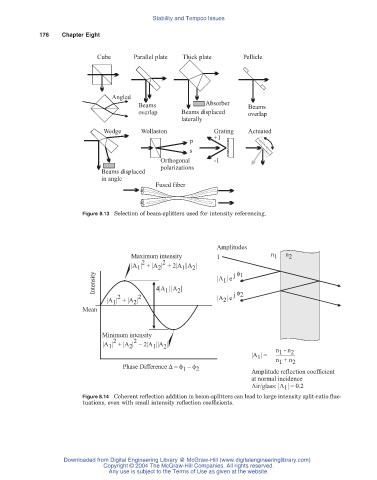
                        Figure 8.13 Selection of beam-splitters used for intensity referencing.


                                                             Amplitudes
                                      Maximum intensity      1              n 1  n 2
                                        2     2
                                     |A |  + |A |  + 2|A ||A |     f
                                                    1
                                             2
                                       1
                                                      2
                           Intensity        4|A | |A |       |A | e  j 1
                                                               1
                                                                   f
                                  2    2       1  2          |A | e  j 2
                               |A |  + |A |                    2
                                      2
                                1
                        Mean
                             Minimum intensity
                                2     2
                              |A |  + |A | – 2|A ||A |
                                              2
                                            1
                                     2
                               1
                                                                              n  - n 2
                                                                               1
                                                                       |A | =
                                                                         1
                                                                              n  + n 2
                                                                               1
                                   Phase Difference D = f  –  f        Amplitude reflection coefficient
                                                    1
                                                       2
                                                                       at normal incidence
                                                                       Air/glass: |A 1 | = 0.2
                        Figure 8.14 Coherent reflection addition in beam-splitters can lead to large intensity split-ratio fluc-
                        tuations, even with small intensity reflection coefficients.
                   Downloaded from Digital Engineering Library @ McGraw-Hill (www.digitalengineeringlibrary.com)
                              Copyright © 2004 The McGraw-Hill Companies. All rights reserved.
                               Any use is subject to the Terms of Use as given at the website.
   178   179   180   181   182   183   184   185   186   187   188