
Page 189 - Photodetection and Measurement - Maximizing Performance in Optical Systems
P. 189
Stability and Tempco Issues
182 Chapter Eight
laser light received on one detector (top curve). It can be seen that the noise
level over most of this low frequency region is 20dB higher than the shot limit.
The central curve shows the result of subtracting an almost identical reference
current obtained from the same beam with a beam-splitter from the signal pho-
tocurrent. The two received powers have been manually adjusted to almost null
out the DC photocurrent. If this were done with two shot-noise limited signals,
the uncorrelated noise powers would add, increasing the measured noise power
by 3dB. In fact, the noise drops to within 4dB of the shot noise level. The even
lower dark noise shows that amplifier noise is insignificant, even with visible
power supply harmonics.
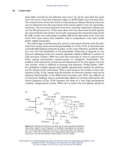
One advantage of performing this current subtraction directly with the pho-
tocurrents using series-connected photodiodes as in Fig. 8.18a is that there are
no bandwidth limiting elements in place, so the noise reduction should be effec-
tive over the full bandwidth of the photodiode. Otherwise it depends on the
dynamic balancing of the two receiver channels, which is difficult to achieve to
high precision. Houser (1994) has used this technique to make 0.1 percent pre-
cision optical transmission measurements in megahertz bandwidths. The
problem with subtraction is that manual adjustment of the two signals must be
very precise, which is difficult to arrange and maintain. Philip Hobbs (1997)
has published a highly elegant and capable optoelectronic module for perform-
ing the photocurrent subtraction. This is equivalent to the simple current sub-
traction of Fig. 8.18a, except that the fraction of reference current used can be
adjusted electronically in the differential transistor pair. With the addition of
an electronic feedback loop to automatically adjust the current subtraction, the
circuit fragment of Fig. 8.18b becomes the basis of a very high performance
intensity compensation system. With care to match the two optical signals by
(a) (b)
+12V
Signal
Transimpedance R
+12V f
Signal MPSA-64 33k
1 / 4 OP420
I -I - Linear
s r
output
C 2μ2 R
+
Reference MAT-04FP 1k
1 8 1k
-12V 2 9 -
3 10 26R +
1 / 4 OP420
Log
Reference output
-12V
Figure 8.18 Signal and reference currents can be automatically subtracted
using this elegant circuit fragment. A feedback loop adjusts the propor-
tion of the reference photocurrent that is subtracted from the signal to
give zero. This allows intensity noise suppression right down to the shot
noise limit. Circuit reproduced by permission of P.C.D. Hobbs.
Downloaded from Digital Engineering Library @ McGraw-Hill (www.digitalengineeringlibrary.com)
Copyright © 2004 The McGraw-Hill Companies. All rights reserved.
Any use is subject to the Terms of Use as given at the website.