Page 194 - Photodetection and Measurement - Maximizing Performance in Optical Systems
P. 194

Stability and Tempco Issues

                                                                   Stability and Tempco Issues  187


                       Sources                    Detectors
                                        L
                         S 1             11          D 1
                                           L 12
                         S 2                         D 2
                                            L 13
                         S 3                         D 3
                                    a        L 14
                         S 4                         D 4


                                        L
                       Figure 8.22 More sources, detectors, and
                       path permutations can improve absorption
                       resolution.


                       Modulated                                    Monitor
                       LED source                                   photodiode
                               1mW               0.5mW
                                                                            To ref. channel
                                                                            demodulation
                                                             3.6% reflection
                                                             (18μW)
                                                 0.5mW
                                     Polished fiber                         Liquid
                                     coupler                                under test
                             Signal                                 50μW
                             photodiode
                                          Sensor fiber:
                                          10dB one-way loss
                         To signal channel
                         demodulation                                      n:1.33-1.40
                                                       0.06–0.25% reflection
                                                       (30nW-125nW)
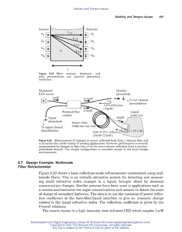
                       Figure 8.23 Measurement of changes in power reflected back from a distant fiber end
                       is attractive for a wide variety of sensing applications. However, performance is severely
                       compromised by changes in fiber loss, or by the more intense reflection from a monitor-
                       photodiode branch. The simple configuration is unusable except in the most benign
                       environments.

           8.7 Design Example: Multimode
           Fiber Refractometer

                       Figure 8.23 shows a basic reflection-mode refractometer constructed using mul-
                       timode fibers. This is an initially attractive system for detecting and measur-
                       ing small refractive index changes in a liquid, brought about by chemical
                       concentration changes. Similar systems have been used in applications such as
                       a remote saccharimeter for sugar concentrations and sensors to detect the state
                       of charge of secondary batteries. The idea is to use the variation of power reflec-
                       tion coefficient at the bare-fiber/liquid interface to give an intensity change
                       related to the liquid refractive index. The reflection coefficient is given by the
                       Fresnel relations.
                         The source chosen is a high intensity near-infrared LED which couples 1mW


                   Downloaded from Digital Engineering Library @ McGraw-Hill (www.digitalengineeringlibrary.com)
                              Copyright © 2004 The McGraw-Hill Companies. All rights reserved.
                               Any use is subject to the Terms of Use as given at the website.
   189   190   191   192   193   194   195   196   197   198   199