
Page 192 - Photodetection and Measurement - Maximizing Performance in Optical Systems
P. 192
Stability and Tempco Issues
Stability and Tempco Issues 185
D 1
L 11
S 1
From I/O ports on
microcontroller D L a - Ch.1
G 12 +
S
L 21
2x D 2
10k L 22
S 2
D - Ch.2
G +
S To ADCs and
2x microcontroller
ZVN2106A
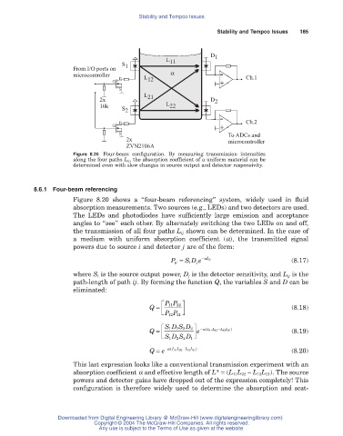
Figure 8.20 Four-beam configuration. By measuring transmission intensities
along the four paths L ij, the absorption coefficient of a uniform material can be
determined even with slow changes in source output and detector responsivity.
8.6.1 Four-beam referencing
Figure 8.20 shows a “four-beam referencing” system, widely used in fluid
absorption measurements. Two sources (e.g., LEDs) and two detectors are used.
The LEDs and photodiodes have sufficiently large emission and acceptance
angles to “see” each other. By alternately switching the two LEDs on and off,
the transmission of all four paths L ij shown can be determined. In the case of
a medium with uniform absorption coefficient (a), the transmitted signal
powers due to source i and detector j are of the form:
P ij = S D e -a L ij (8.17)
i
j
where S i is the source output power, D j is the detector sensitivity, and L ij is the
path-length of path ij. By forming the function Q, the variables S and D can be
eliminated:
È PP ˘
11 22
Q = (8.18)
Í Î PP ˚ ˙
21
12
È 1 1 2 2 a L L )
e
Q = SD S D ˘ - ( 11 22 (8.19)
LL - 12 21
Í Î SD S D ˚ ˙
2
2
1
1
a
Q = e - ( 11 22 L L ) (8.20)
LL - 12 21
This last expression looks like a conventional transmission experiment with an
absorption coefficient a and effective length of L* = (L 11L 22 - L 12L 21). The source
powers and detector gains have dropped out of the expression completely! This
configuration is therefore widely used to determine the absorption and scat-
Downloaded from Digital Engineering Library @ McGraw-Hill (www.digitalengineeringlibrary.com)
Copyright © 2004 The McGraw-Hill Companies. All rights reserved.
Any use is subject to the Terms of Use as given at the website.