
Page 196 - Photodetection and Measurement - Maximizing Performance in Optical Systems
P. 196
Stability and Tempco Issues
Stability and Tempco Issues 189
This is three orders of magnitude larger than the peak signal from the process
liquid, and modulated at the same frequency! In order to resolve even ten refrac-
tive index values with this system the total stability of all reflection coefficients
and fiber attenuation values would have to be about 20,000:1. This is not impos-
sible, but represents an extremely high performance system.
Clearly the sensor fiber loss is a big problem, so we might attempt to find an
alternative fiber with lower loss. However, even if the sensor fiber loss were
reduced to zero, the monitor diode reflection (9.0mW) would still dominate the
maximum primary received signal (now 625nW). Hence the next job is to reduce
the monitor diode reflection, and we have several options. Antireflection coat-
ings in the form of quarter-wave thickness films of geometric-mean refractive
index deposited on the fiber end can in principle reduce the reflection to zero.
In practice, restricted choice of coating materials, errors in deposition, the
refractive index gradient across the fiber core diameter and the spread of prop-
agation angles in the coating conspire to reduce the coating performance. We
might expect 0.25 percent power reflection coefficient, or about 625nW at the
signal photodiode.
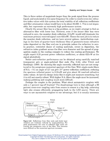
Better anti-reflection performance can be obtained using carefully matched
transparent gels or angle-polished fiber ends (Fig. 8.24), after Ulrich and
Rashleigh (1980). By choosing the angle correctly, reflected rays are not recap-
tured in the acceptance numerical aperture of the fiber. With single-mode fibers
-6
of N.A. ª 0.1 an angle of 12° can give 10 power reflection coefficient, reducing
the spurious reflected power to 0.25nW and give about 20 resolved refractive
index values. At last the design looks like it might just measure something, but
it is still not exactly robust. With higher N.A. fibers the angle must be increased,
making polishing and coupling much more difficult.
Perhaps the coupler is the problem. What about asymmetric couplers with
only a 1 percent tap-off fraction? The disadvantage here is that although a 99
percent cross-over coupling ratio from source to sensor is a big help, returning
light also crosses efficiently, propagating back to the LED source. There are
ways to use asymmetric couplers to our advantage, but it is usually necessary
Polish
q angle
Range of
incident angles
Range of
output angles
Range of
reflected angles
Figure 8.24 Reflections from fiber ends and diode laser
windows are routinely reduced by angle-polishing. For
good performance the cone of reflected light must not
overlap the acceptance cone of the fiber. This becomes
more difficult as the numerical aperture increases.
Downloaded from Digital Engineering Library @ McGraw-Hill (www.digitalengineeringlibrary.com)
Copyright © 2004 The McGraw-Hill Companies. All rights reserved.
Any use is subject to the Terms of Use as given at the website.