
Page 201 - Photodetection and Measurement - Maximizing Performance in Optical Systems
P. 201
Contamination and Industrial Systems
194 Chapter Nine
Absorbing
biofilm
a
Source } 1 P
S 1 11
} a 2 Two beams see
similar film thicknesses
Domed
window P 12
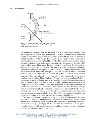
Figure 9.3 Domed windows can equalize the absorb-
ing film atternuations, but at the risk of greater
speed of contamination growth.
if the deposited films vary on a scale much finer than source and detector, then
the compensation should also be effective. The real problems arise where the
fouling is structured at just the wrong scale. We could say that the density of
fouling variations with spatial frequencies of the order of the reciprocal of
source/detector dimensions should be low to obtain good compensation. Stated
less pretentiously, dirty blobs about the same size as source or detector (Fig.
9.4a) are bad news! They cause the attenuation to be different for the straight-
through (P ii) and cross (P ij) beams. One help is to make the sources and detec-
tors much larger than the typical blob size (Fig. 9.4b). In pumped-sample on-line
instruments with small cells, the options for this are rather limited. However,
where a four-beam attenuation measurement system is to be immersed in the
large scale flowing water stream typical of a water treatment works, size is
hardly a consideration. There is plenty of space and sample available. It there-
fore seems surprising that no one, to my knowledge, manufactures instruments
with sources the size of car headlamps, and solar-cell detectors almost as large.
Lamps made up from dozens of light emitting diodes are becoming common for
illumination and display applications, which would be ideal for such a large-
format turbidity or optical absorption instrument. They could still be modu-
lated at high speed for synchronous detection, and are likely to provide much
more robust measurements, both in the face of severe contamination build-up
and with nonuniform samples such as raw sewage and effluents.
The basic four-beam configuration of Fig. 9.1 is probably about right for many
applications, aided by optoelectronic components chosen with regard to the
structure of the fouling layers expected, and especially if helped by occasional
automatic cleaning. Although perfection is unlikely, some form of fouling com-
pensation using multibeam referencing with plane windows should be designed
in to all but the most basic instrument.
Downloaded from Digital Engineering Library @ McGraw-Hill (www.digitalengineeringlibrary.com)
Copyright © 2004 The McGraw-Hill Companies. All rights reserved.
Any use is subject to the Terms of Use as given at the website.