
Page 200 - Photodetection and Measurement - Maximizing Performance in Optical Systems
P. 200
Contamination and Industrial Systems
Contamination and Industrial Systems 193
system does help, and transmission reduction to 10 percent of that of the clean
state can usually be encompassed. Nevertheless, the reduction in light will cer-
tainly reduce the S/N and increase errors due to the numerical division
processes involved in compensation. The technique is used both for liquid
absorption measurements using four transmission determinations, as well as
for turbidity measurements with determination of two transmitted and two
scattered intensities. Other combinations and geometrical arrangements are
possible. The electronic division limitations are not fundamental, and could in
principle be lifted through higher resolution ADCs, brighter, self-adjusting
sources, etc. We should really be asking what are the remaining fundamental
limits of the technique which preclude perfect compensation?
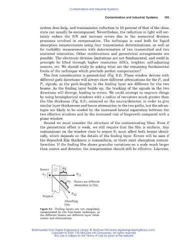
The first consideration is geometrical (Fig. 9.2). Plane window devices with
different path directions will always show different attenuations for the P ii and
P ij signals, as the path-lengths in the fouling layer are different for the two
beams. As the fouling layer builds up, the tracking of the signals in the two
directions will diverge, leading to errors. We could attempt to improve things
by using hemispherical windows with a radius of curvature much greater than
the film thickness (Fig. 9.3), centered on the source/detector, in order to give
similar layer thicknesses and hence attenuation in the two paths, but the advan-
tages are likely to be eroded by the increased lateral separation between the
two effective windows and by the increased risk of biogrowth compared with a
plane window.
Second we must consider the structure of the contaminating films. Even if
the geometrical effect is weak, we still require that the film is uniform. Any
contaminant on the window close to source S 1 must affect both beams identi-
cally, which depends on the details of the fouling layer. Errors will be seen if
the deposited film thickness is nonuniform, or there exist absorption nonuni-
formities. If the fouling film shows granular variations on a scale much larger
than source and detector, the compensation should still be effective. Likewise,
Source 1 } a
S 1 P 11
} a 2 Beams see different
attenuation in film
P 12
Window
Absorbing
film
Figure 9.2 Fouling layers are not completely
compensated by the four-beam technique, as
the different beams see different layer thick-
nesses and attenuations.
Downloaded from Digital Engineering Library @ McGraw-Hill (www.digitalengineeringlibrary.com)
Copyright © 2004 The McGraw-Hill Companies. All rights reserved.
Any use is subject to the Terms of Use as given at the website.