
Page 235 - Photodetection and Measurement - Maximizing Performance in Optical Systems
P. 235
Measurand Modulation
228 Chapter Ten
3.6% reflection
Source 1mW (18μW)
Reference
channel
0.5mW
9μW + Fiber coupler
1.5nW 50:50
50μW AR-coated
fiber end
Sensor fiber:
Signal channel 10dB one-way loss
m W crystal controlled
motor-driven modulator
(watch-motor) Liquid under test
n:1.33-1.40
R = 0.06% - 0.25%
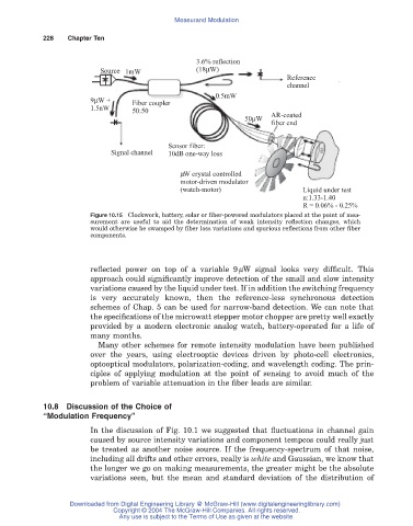
Figure 10.15 Clockwork, battery, solar or fiber-powered modulators placed at the point of mea-
surement are useful to aid the determination of weak intensity reflection changes, which
would otherwise be swamped by fiber loss variations and spurious reflections from other fiber
components.
reflected power on top of a variable 9mW signal looks very difficult. This
approach could significantly improve detection of the small and slow intensity
variations caused by the liquid under test. If in addition the switching frequency
is very accurately known, then the reference-less synchronous detection
schemes of Chap. 5 can be used for narrow-band detection. We can note that
the specifications of the microwatt stepper motor chopper are pretty well exactly
provided by a modern electronic analog watch, battery-operated for a life of
many months.
Many other schemes for remote intensity modulation have been published
over the years, using electrooptic devices driven by photo-cell electronics,
optooptical modulators, polarization-coding, and wavelength coding. The prin-
ciples of applying modulation at the point of sensing to avoid much of the
problem of variable attenuation in the fiber leads are similar.
10.8Discussion of the Choice of
“Modulation Frequency”
In the discussion of Fig. 10.1 we suggested that fluctuations in channel gain
caused by source intensity variations and component tempcos could really just
be treated as another noise source. If the frequency-spectrum of that noise,
including all drifts and other errors, really is white and Gaussian, we know that
the longer we go on making measurements, the greater might be the absolute
variations seen, but the mean and standard deviation of the distribution of
Downloaded from Digital Engineering Library @ McGraw-Hill (www.digitalengineeringlibrary.com)
Copyright © 2004 The McGraw-Hill Companies. All rights reserved.
Any use is subject to the Terms of Use as given at the website.