
Page 242 - Photodetection and Measurement - Maximizing Performance in Optical Systems
P. 242
Multiple Channel Detection
Multiple Channel Detection 235
each is driven with the same current, modulated at the same frequency f 1 for
quantification using two lock-in amplifiers.
While the brute-force approach will be effective, its color filters are expen-
sive, especially if they must be custom sawn into small pieces or odd shapes.
Further, the filters enforce separation between the two beams which means
that the two channels never probe precisely the same sample. This can be very
significant in on-line applications such as industrial manufacturing and water
treatment processes, where inhomogeneities and even multiphase flows
exist. It can also be a problem in laboratory analyses, due to poor mixing of
reagents, settlement and nonuniform adsorption of materials onto the con-
tainer walls. Improved performance is likely if we overlap the optical paths
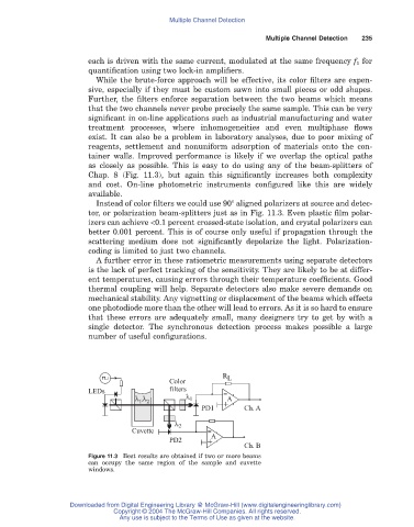
as closely as possible. This is easy to do using any of the beam-splitters of
Chap. 8 (Fig. 11.3), but again this significantly increases both complexity
and cost. On-line photometric instruments configured like this are widely
available.
Instead of color filters we could use 90° aligned polarizers at source and detec-
tor, or polarization beam-splitters just as in Fig. 11.3. Even plastic film polar-
izers can achieve <0.1 percent crossed-state isolation, and crystal polarizers can
better 0.001 percent. This is of course only useful if propagation through the
scattering medium does not significantly depolarize the light. Polarization-
coding is limited to just two channels.
A further error in these ratiometric measurements using separate detectors
is the lack of perfect tracking of the sensitivity. They are likely to be at differ-
ent temperatures, causing errors through their temperature coefficients. Good
thermal coupling will help. Separate detectors also make severe demands on
mechanical stability. Any vignetting or displacement of the beams which effects
one photodiode more than the other will lead to errors. As it is so hard to ensure
that these errors are adequately small, many designers try to get by with a
single detector. The synchronous detection process makes possible a large
number of useful configurations.
R L
Color
LEDs filters
l ,l l 1 + A
1 2
-
PD1 Ch. A
l 2
Cuvette
+ A
PD2
-
Ch. B
Figure 11.3 Best results are obtained if two or more beams
can occupy the same region of the sample and cuvette
windows.
Downloaded from Digital Engineering Library @ McGraw-Hill (www.digitalengineeringlibrary.com)
Copyright © 2004 The McGraw-Hill Companies. All rights reserved.
Any use is subject to the Terms of Use as given at the website.