
Page 245 - Photodetection and Measurement - Maximizing Performance in Optical Systems
P. 245
Multiple Channel Detection
238 Chapter Eleven
imperfect phase adjustment. Nevertheless, the lock-in realization of this
approach makes a highly didactic demonstration, which for moderate isolation
is effective.
11.4.2 Multimode fiber refractometer
revisited—again
In the design of a simple refractometer for remote liquid refractive index meas-
urement shown in Chapter 8 we wanted to measure two signals, one a refer-
ence intensity representing the power coupled into the fiber system, the other
a variable intensity reflected from the sensing fiber end. One problem was how
to suppress the reflection from the monitor fiber arm to very low levels (at least
-60dB), such that it does not perturb the weak reflection from the sensing
probe. One way to do this is to treat it as a two-channel measurement system,
and to apply the two-phase detection technique.
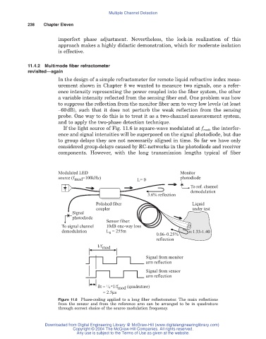
If the light source of Fig. 11.6 is square-wave modulated at f mod, the interfer-
ence and signal intensities will be superposed on the signal photodiode, but due
to group delays they are not necessarily aligned in time. So far we have only
considered group-delays caused by RC-networks in the photodiode and receiver
components. However, with the long transmission lengths typical of fiber
Modulated LED Monitor
source (f mod =100kHz) L= 0 photodiode
To ref. channel
demodulation
3.6% reflection
Polished fiber Liquid
coupler under test
Signal
photodiode
Sensor fiber:
To signal channel 10dB one-way loss
demodulation L = 255m n:1.33-1.40
s
0.06–0.25%
reflection
1/f mod
Signal from monitor
arm reflection
Signal from sensor
arm reflection
d t = 1 / 4 *1/f mod (quadrature)
= 2.5μs
Figure 11.6 Phase-coding applied to a long fiber reflectometer. The main reflections
from the sensor and from the reference arm can be arranged to be in quadrature
through correct choice of the source modulation frequency.
Downloaded from Digital Engineering Library @ McGraw-Hill (www.digitalengineeringlibrary.com)
Copyright © 2004 The McGraw-Hill Companies. All rights reserved.
Any use is subject to the Terms of Use as given at the website.