
Page 244 - Photodetection and Measurement - Maximizing Performance in Optical Systems
P. 244
Multiple Channel Detection
Multiple Channel Detection 237
However, this is not the only source of interchannel interference. We saw that
square-wave demodulation produces harmonic responses at 3f mod, 5f mod, etc. If
the detected signals are also not perfectly sinusoidal, they will contain energy
at these harmonics which will be detected to some extent by the harmonic
responses. It is therefore also necessary to avoid overlaps of these harmonics
from different frequencies f mod, matching to within the detection bandwidth. It
is probably only worth worrying about the first few coincidences, for example
3 ¥ f 1mod ª 5 ¥ f 2mod, but if the application is critical or the performance
marginal, all such coincidences must be investigated and their interactions
measured.
11.4 Two-Phase Detection
11.4.1 Sine/cosine modulation and detection
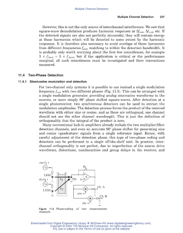
For two-channel only systems it is possible to use instead a single modulation
frequency f mod with two different phases (Fig. 11.5). This can be arranged with
a single modulation generator, providing analog sine/cosine waveforms to the
sources, or more simply 90° phase shifted square-waves. After detection at a
single photoreceiver, two synchronous detectors can be used to extract the
modulation amplitudes. The detection process forms the product of the received
waveform with either sine or cosine, and as these are orthogonal, one channel
should not see the other channel wavelength. This is just the definition of
orthogonality, that the integral of the product is zero.
Many conventional lock-in amplifiers already include the two multiplier/filter
detection channels, and even an accurate 90° phase shifter for generating sine
and cosine (quadrature) signals from a single reference input. Hence, with
careful adjustment of the detection phase, this type of two-phase coding and
detection can be performed in a single off-the-shelf unit. In practice, inter-
channel orthogonality is not perfect, due to imperfection of the source drive
waveforms, distortions, nonlinearities and group delays in the receiver, and
cos f t
1
R L
LED1 + A
sin f t l 1 PD
1
-
Ch. A
l 2
LED2
cos
Ch. B
sin
Figure 11.5 Phase-coding of two measurement
channels.
Downloaded from Digital Engineering Library @ McGraw-Hill (www.digitalengineeringlibrary.com)
Copyright © 2004 The McGraw-Hill Companies. All rights reserved.
Any use is subject to the Terms of Use as given at the website.