
Page 152 - Photonics Essentials an introduction with experiments
P. 152
Lasers
146 Photonic Devices
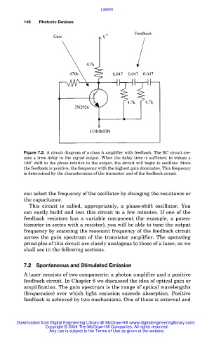
Figure 7.2. A circuit diagram of a class A amplifier with feedback. The RC circuit cre-
ates a time delay in the signal output. When the delay time is sufficient to induce a
180° shift in the phase relative to the output, the circuit will begin to oscillate. Since
the feedback is positive, the frequency with the highest gain dominates. This frequency
is determined by the characteristics of the transistor and of the feedback circuit.
can select the frequency of the oscillator by changing the resistance or
the capacitance.
This circuit is called, appropriately, a phase-shift oscillator. You
can easily build and test this circuit in a few minutes. If one of the
feedback resistors has a variable component (for example, a poten-
tiometer in series with a resistor), you will be able to tune the output
frequency by scanning the resonant frequency of the feedback circuit
across the gain spectrum of the transistor amplifier. The operating
principles of this circuit are closely analogous to those of a laser, as we
shall see in the following sections.
7.2 Spontaneous and Stimulated Emission
A laser consists of two components: a photon amplifier and a positive
feedback circuit. In Chapter 6 we discussed the idea of optical gain or
amplification. The gain spectrum is the range of optical wavelengths
(frequencies) over which light emission exceeds absorption. Positive
feedback is achieved by two mechanisms. One of these is external and
Downloaded from Digital Engineering Library @ McGraw-Hill (www.digitalengineeringlibrary.com)
Copyright © 2004 The McGraw-Hill Companies. All rights reserved.
Any use is subject to the Terms of Use as given at the website.