
Page 169 - Physical Principles of Sedimentary Basin Analysis
P. 169
6.13 Heat flow in fractures 151
1 sinh(Pe(1 −ˆz)/2) nπ
sin(πnˆz) dˆz =− (6.186)
2
0 sinh(Pe/2) (nπ) + (Pe/2) 2
1
(1 −ˆz) exp(−Pe ˆz/2) sin(πnˆz) dˆz
0
2 2 n
nπ (nπ) − Pe + (Pe/2) + (−1) Pe exp(Pe/2)
= . (6.187)
2 2 2
(nπ) + (Pe/2)
These integrals can be obtained after some work, or more easily with the help of tables of
integrals.
6.13 Heat flow in fractures
Figure 6.22 shows a fracture connecting two aquifers. The fracture drains fluid from the
lowest aquifer, which is discharged into the highest aquifer. This situation is quite similar to
the one in Figure 6.17, except that the fluid now flows upwards. Another difference is that
the vertical fluid flow, which took place over a wide area in Figure 6.17, is now assumed
to be confined to a narrow fracture. We saw in Section 6.11 that fluid flow could increase
the temperature beyond the conductive temperature solution. The parameter that controls
the amount of convective heat transfer was shown in Section 6.12 to be the Peclet number.
The regime defined by Pe
1 is conduction-dominated, while the other regime Pe
1is
convection-dominated.
Heat transfer in and around the rectangular fracture in Figure 6.22 differs from the 1D
vertical heat flow in Figure 6.17 by being a 2D problem. The conductive heat flow in the
rock surrounding the fracture has a horizontal component when the fracture is heated above
1.0
0.1
0.8 0.2
0.3
0.4
0.6
z [−] 0.5
^ 0.6
0.4
0.7
0.2 0.8
0.9
0.0
0.0 0.2 0.4 0.6 0.8 1.0
^ x [−]
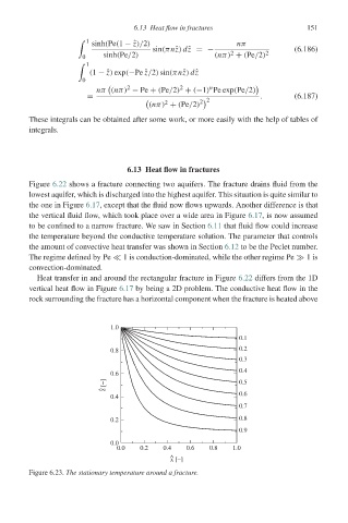
Figure 6.23. The stationary temperature around a fracture.