
Page 135 - Pipeline Risk Management Manual Ideas, Techniques, and Resources
P. 135
5/112 Design Index
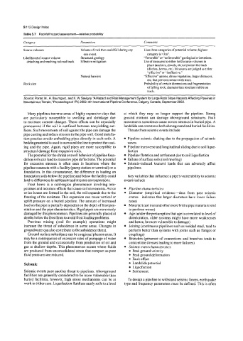
Table 5.7 Rockfall hazard assessment-elative probability
Category Pammeters Comments
Source volumes Volume of rock that could fall during any Uses three categories ofpotential volume; highest
one event. category is >3m3.
Likelihood of source volume Structural geology “Favorable” or “unfavorable” geological orientations.
detaching and reaching railroad track Effective mitigation Use ofmeasures to either hold source volumes in
place (anchors, dowels, etc) or protect the track
(ditches, berms, etc). Measures are judged as either
“effective” or “ineffective.”
Natural barriers “Effective” aprons, dense vegetation, larger distances,
etc. that prevent contact with track.
Rock size Probability of certain dimensions and fragmentation
of falling rock; characterizes resultant rubble on
track.
Source: Porter, M., A. Baumgard, and K. W. Savigny, “A Hazard and Risk Management System for Large Rock Slope Hazards Affecting Pipelines in
Mountainous Terrain,” Proceedings of IPC 2002: 4th International Pipeline Conference, Calgary, Canada, September 2002.
Many pipelines traverse areas of highly expansive clays that at which they may no longer support the pipeline. Strong
are particularly susceptible to swelling and shrinkage due ground motions can damage aboveground structures. Fault
to moisture content changes. These effects can be especially movements sometimes cause severe stresses in buried pipe. A
pronounced if the soil is confined between nonyielding sur- landslide can overstress both aboveground and buried facilities.
faces. Such movements of soil against the pipe can damage the Threats from seismic events include
pipe coating and induce stresses in the pipe wall. Good installa-
tion practice avoids embedding pipes directly in such soils. A Pipeline seismic shaking due to the propagation of seismic
bedding material is used to surround the line to protect the coat- waves
ing and the pipe. Again, rigid pipes are more susceptible to Pipeline transverse and longitudinal sliding due to soil lique-
structural damage from expansive soils. faction
The potential for the shrink or swell behavior ofpipeline foun- Pipeline flotation and settlement due to soil liquefaction
dation soils can lead to excessive pipe deflections. The potential Failure of surface soils (soil raveling)
for excessive stresses is often seen in locations where the Seismic-induced tsunami loads that can adversely affect
pipeline connects with a facility (pump station or terminal) on a pipelines.
foundation. In this circumstance, the difference in loading on
foundation soils below the pipeline and below the facility could Key variables that influence a pipe’s vulnerability to seismic
lead to differences in settlement and stresses on connections. events include
Frost heave is a cold-region phenomenon involving tem-
perature and moisture effects that cause soil movements. As ice Pipeline characteristics
or ice lenses are formed in the soil, the soil expands due to the Diameter (empirical evidencedata from past seismic
freezing of the moisture. This expansion can cause vertical or events-indicates that larger diameters have lower failure
uplift pressure on a buried pipeline. The amount of increased rates)
load on the pipe is partially dependent on the depth of frost pen- Material (cast iron and other more brittle pipe materials tend
etration and the pipe characteristics. Rigid pipes are more easily to perform worse)
damaged by this phenomenon. Pipelines are generally placed at Age (under the presumption that age is correlated to level of
depths below the frost lines to avoid frost loading problems. deterioration, older systems might have more weaknesses
Previous mining (coal for example) operations might and hence, be more vulnerable to damage)
increase the threat of subsidence in some areas. Changes in Joining (continuous pipelines such as welded steel, tend to
groundwater can also contribute to the subsidence threat. perform better than systems with joints such as flanges or
Ground surface subsidence can be a regional phenomenon. It couplings)
may be a consequence of excessive rates of pumpage of water Branches (presence of connections and branches tends to
from the ground and occasionally from production of oil and concentrate stresses leading to more failures)
gas at shallow depths. This phenomenon occurs where fluids Seismic event characteristics
are produced from unconsolidated strata that compact as pore 0 Peak ground velocity
fluid pressures are reduced. Peak ground deformation
Faultoffset
Seismic Landslide potential
Liquefaction
Seismic events pose another threat to pipelines. Aboveground Settlement.
facilities are generally considered to be more vulnerable than
buried facilities, however, high stress mechanisms can be at To design a pipeline to withstand seismic forces, earthquake
work in either case. Liquefaction fluidizes sandy soils to a level type and frequency parameters must be defined. This is often