
Page 148 - Pipeline Rules of Thumb Handbook
P. 148
Hydrostatic Testing 135
86.6psig (200 feet ¥ 0.433 = 86.6psig). A test pressure equal
to 90% of SMYS is 1,404psig. Since the test site is lower
than the high end of the line, the 86.6psig is added to
1,404psig to obtain a test site pressure of 1,491psig. The pres-
sure at the end of the line will be 1,404psig which equates to
90% of SMYS. The pressure at the low point equates to 96%
of SMYS.
Now, let’s assume a line has a high point elevation of 1,100
feet, a low elevation point of 1,000 feet, and the elevation
at the test site is 1,050 feet. The test pressure at the high
point will need to be 1,404psig in order to meet the
90% of SMYS requirement. The pressure at the low point
will be 1,447psig, and the pressure at the test site will be
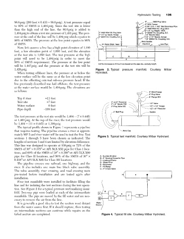
1,426psig. Figure 2. Typical pressure manifold. Courtesy Milbar
When testing offshore lines, the pressure at or below the Hydrotest.
water surface will be the same as at the low elevation point
due to the offsetting external sub-sea pressure head. If the
line previously described was laid offshore, the test pressure
at the water surface would be 1,404psig. The elevations are
as follows:
Top if riser +11 feet
Test site +7 feet
Water surface 0 feet
Pipe depth -168 feet
The test pressure at the test site would be 1,404 - (7 ¥ 0.445)
or 1,401psig. At the top of the riser, the test pressure would
be 1,404 - (11 ¥ 0.445) or 1,399psig.
The typical profile shown in Figure 1 represents a pipeline
that requires testing. The pipeline crosses a river at approxi-
mately MP 5 and river water will be used to test the line. Test
Figure 3. Typical test manifold. Courtesy Milbar Hydrotest.
sections 1 through 5 have been chosen as indicated. The
lengths of sections 3 and 4 are limited by elevation difference.
This line was designed to operate at 936psig or 72% of the
SMYS of 30≤¥ 0.375≤wt API 5LX X52 pipe for Class I loca-
tions, and 60% of the SMYS of 30≤¥ 0.390≤wt API 5LX X60
pipe for Class II locations, and 50% of the SMYS of 30≤¥
0.438≤wt API 5LX X65 for Class III locations.
The pipeline crosses one railroad, one highway, and the
river. It also includes one main line block valve assembly.
The valve assembly, river crossing, and road crossing were
pre-tested before installation and are tested again after
installation.
Four test manifolds were installed to facilitate filling the
line and for isolating the test sections during the test opera-
tion. See Figure 2 for a typical pressure sectionalizing mani-
fold. Two-way pigs were loaded at each of the intermediate
manifolds. The pigs are moved by the fill water and are nec-
essary to remove the air from the line.
It is generally a good idea to test the section most distant
from the water source first. If it should rupture, then testing
on intermediate sections can continue while repairs on the
failed section are completed. Figure 4. Typical fill site. Courtesy Milbar Hydrotest.