
Page 149 - Pipeline Rules of Thumb Handbook
P. 149
136 Pipeline Rules of Thumb Handbook
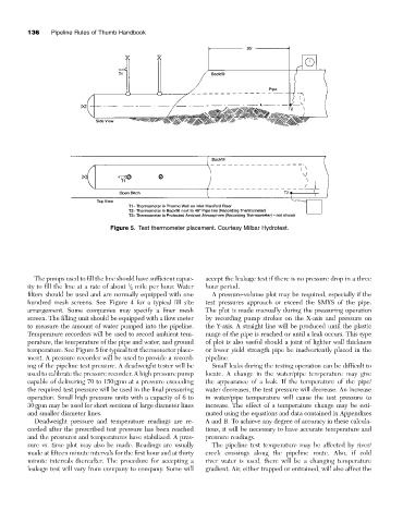
Figure 5. Test thermometer placement. Courtesy Milbar Hydrotest.
The pumps used to fill the line should have sufficient capac- accept the leakage test if there is no pressure drop in a three
1
ity to fill the line at a rate of about / 2 mile per hour. Water hour period.
filters should be used and are normally equipped with one A pressure-volume plot may be required, especially if the
hundred mesh screens. See Figure 4 for a typical fill site test pressures approach or exceed the SMYS of the pipe.
arrangement. Some companies may specify a finer mesh The plot is made manually during the pressuring operation
screen. The filling unit should be equipped with a flow meter by recording pump strokes on the X-axis and pressure on
to measure the amount of water pumped into the pipeline. the Y-axis. A straight line will be produced until the plastic
Temperature recorders will be used to record ambient tem- range of the pipe is reached or until a leak occurs. This type
perature, the temperature of the pipe and water, and ground of plot is also useful should a joint of lighter wall thickness
temperature. See Figure 5 for typical test thermometer place- or lower yield strength pipe be inadvertently placed in the
ment. A pressure recorder will be used to provide a record- pipeline.
ing of the pipeline test pressure. A deadweight tester will be Small leaks during the testing operation can be difficult to
used to calibrate the pressure recorder. A high pressure pump locate. A change in the water/pipe temperature may give
capable of delivering 70 to 150gpm at a pressure exceeding the appearance of a leak. If the temperature of the pipe/
the required test pressure will be used in the final pressuring water decreases, the test pressure will decrease. An increase
operation. Small high pressure units with a capacity of 6 to in water/pipe temperature will cause the test pressure to
30gpm may be used for short sections of large diameter lines increase. The effect of a temperature change may be esti-
and smaller diameter lines. mated using the equations and data contained in Appendixes
Deadweight pressure and temperature readings are re- A and B. To achieve any degree of accuracy in these calcula-
corded after the prescribed test pressure has been reached tions, it will be necessary to have accurate temperature and
and the pressures and temperatures have stabilized. A pres- pressure readings.
sure vs. time plot may also be made. Readings are usually The pipeline test temperature may be affected by river/
made at fifteen minute intervals for the first hour and at thirty creek crossings along the pipeline route. Also, if cold
minute intervals thereafter. The procedure for accepting a river water is used, there will be a changing temperature
leakage test will vary from company to company. Some will gradient. Air, either trapped or entrained, will also affect the