
Page 208 - Pipeline Rules of Thumb Handbook
P. 208
Corrosion/Coatings 195
The mechanism by which the friction coefficient changes in the literature, no comparison to similar tests could be
among the various soils is not apparent from the results of made.
these tests since the soil samples used did not vary consider- Temperatures in the 120°F range should have little or no
ably in description. However, the range over which the factor effect on the coefficient of friction of epoxy to soil.
changes is considerably greater than that previously extrapo-
lated from the literature, i.e.:
Conclusions
Coefficient of friction
Soil description commonly used Although it is virtually impossible to precisely simulate the
Silt 0.3 surface contact situation of a pipeline in a back-filled trench,
Sand 0.4 the test procedure and apparatus reported here are a means
Gravel 0.5 of approximating it. The results indicate that coal tar coatings
have a higher friction resistance than epoxy coatings as far as
The tests also indicate that the moisture content alters the anchoring capabilities of the soil are concerned.
friction factor to some extent, as would be expected. The selection of a coating, based on its soil friction resis-
In order to investigate the influence of temperature, tests tance, could be of economic value in reducing those situations
were conducted with coal tar felt wrapping heated to 120°F. where extreme expansions call for reinforced fittings or elab-
Only a slight softening beneath the coating surface was orate culverts to overcome excessive stress levels in a pipeline
observed, and it is believed that temperatures up to this range system.
will not significantly affect the magnitude of the friction The test results show that previous values commonly used
coefficient. for the coefficient of friction were conservative for similar
soils, and it is suggested that some conservatism still be incor-
Thinfilm epoxy to soils. As expected, results shown porated in future analyses.
in Figure 2 indicate that the friction factor range of 0.51 to Since the tests indicated that the friction coefficient of the
0.71 for the epoxy is somewhat lower than that of the coal epoxies was similar to those previously used for coal tar coat-
tar. ings, their continued use for epoxy coated pipelines should be
Again, the mechanism is not clear, but the results are valid. A more conservative approach to these values is rec-
fairly consistent with the friction coefficient increasing in ommended in soils where the presence of excessive moisture
most instances in the same order of magnitude as for coal could change the friction factor substantially when interfaced
tar. Since such information on this coating was not available with a smooth epoxy coating.
Troubleshooting cathodic protection systems: Magnesium anode system
The basic technique is the same as that outlined above;
more measurements are required, because of the multiplic-
ity of drain points. First, the current output of stations
nearest the point of low potential should be checked; if
these are satisfactory, a similar check should be extended in
both directions until it is clear that the trouble must be on
the line. When a given anode group shows a marked drop in
current output, the cause may be drying out, shrinkage of
backfill, or severed or broken lead wires. If the current is
zero, the pipe-to-soil potential of the lead wire will show
whether it is still connected to the pipe or the anode, and
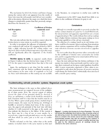
thus indicate the direction to the failure. If the current is Figure 1. Locating Idle Anodes by Surface Potentials. The solid
low, there may be a loss of one or more anodes, by a line shows the potentials found along a line of anodes when all
severed wire; a pipe-to-soil potential survey over the anodes are delivering current; the dotted line exhibits the change when
there is a break in the anode lead at the point indicated. Single
will show which are active, just as in the case of rectifier
disconnected anodes may also be located by this method. A
anodes.
driven ground rod, a pipe lead, or even a rectifier terminal may
Trouble indicated on the line, rather than at the anode be used for the reference ground; all readings should be
stations, is tracked down in the same manner as that used referred to the same reference.