Page 25 - Pipeline Rules of Thumb Handbook
P. 25

12    Pipeline Rules of Thumb Handbook

         B, C, and D; the widths (at the widest part) are one-half, five-  corresponds to the length which runs on the pulley diameter
                                 1
         eighths, seven-eighths and 1/ 8 inches respectively. The com-  which determines the actual speed ratio—about half of the
         plete designation of the belt is the letter showing the width,  depth of the groove. Pitch lengths for A, B, C, and D belts
         followed by the length in inches; thus, an A26 belt is one-half  are greater than their nominal lengths by 1.3, 1.8, 2.9, and 3.3
         inch wide, and 26 inches long on the inside edge. The pitch  inches, respectively.
         length of the belt is measured along a median section, and


         Calculate stress in shaft key


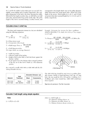
           The shear and compressive stresses in a key are calculated  Example: Determine key stresses for these conditions. . . .
         using the following equations:                        300hP @ 600 RPM; 3≤ dia. shaft, 3/4 ¥ 3/4 key, 4≤ key engage-
                                                               ment length.
                2 T                2 T
         Ss =               Sc =
                                                                                               ,
                                                                                  ,
             d ¥  W ¥  L        d ¥  h ¥  L                     T =  Torque =  HP ¥ 63 000  =  300  ¥ 63 000  = 31 500  in.-lbs
                                     1
                                                                                                       ,
                                                                              RPM           600
         Ss = Shear stress in psi                                     2 T     2  ¥ 31 500
                                                                                   ,
         Sc = Compressive stress in psi                        S s =         =          = 7 000 psi
                                                                                          ,
                                                                   d ¥  W ¥  L  33 4  ¥ 4
                                                                                ¥
                                        ,
                                  HP ¥ 63 000
         T = Shaft torque lb-in. or
                                     RPM                               2 T    2  ¥ 31 500
                                                                                   ,
                                                                                           ,
         d = shaft diameter-inches                             S c =         =          = 14 000 psi
                                                                                     ¥
                                                                                ¥
                                                                        1
         (For taper shafts, use average diameter)                  d ¥  h ¥  L  33 84
         w = width key-inches
         L = effective length of key-inches
         h 1 = height of key in the shaft or hub that bears against the
              keyway—inches
         h 1 = h 2 for square keys. For designs where unequal portions
              of the key are in the hub or shaft, h 1 is the minimum
              portion.
         Key material is usually AISI 1018 or AISI 1045 with the fol-
         lowing allowable stresses:
                                                               The AISI 1018 key should be used since it is within allow-
                                     Allowable Stresses—psi    able stresses. NOTE: If shaft had been 2 3/4≤ dia. (4≤ long
                          Heat                                 hub), the key would be 5/8  ¥ 5/8 and Ss  = 9,200psi, Sc  =
            Material    Treatment     Shear    Compressive
                                                               18,400psi, and a heat treated key—AISI 1045 would have
                                                               been required.
           AISI 1018      None         7,500      15,000
           AISI 1045   225–300 Bhn    15,000      30,000
                                                               Reprinted with permission: The Falk Corporation


         Calculate V-belt length using simple equation


           Rule.                                               where L = Belt length, in.
                                                                     D= Diameter of larger sheave, in.
         L = 1.57(D + d) + 2C                                        d = Diameter of smaller sheave, in.
                                                                     C = Distance between sheave centers, in.
   20   21   22   23   24   25   26   27   28   29   30