
Page 54 - Pipeline Rules of Thumb Handbook
P. 54
Construction 41
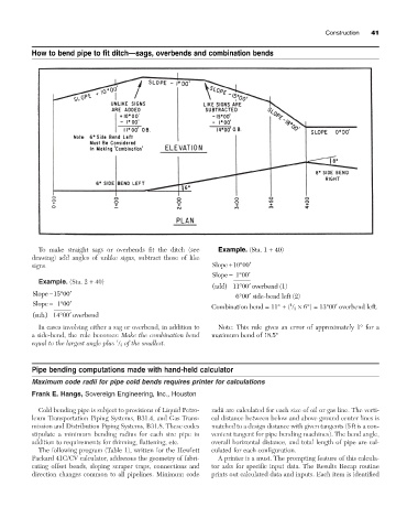
How to bend pipe to fit ditch—sags, overbends and combination bends
To make straight sags or overbends fit the ditch (see Example. (Sta. 1 + 40)
drawing) add angles of unlike signs, subtract those of like
signs. Slope +10 ∞00 ¢
Slope -∞100 ¢
Example. (Sta. 2 + 40)
( add) 11 ∞00 ¢ overbend (1)
Slope -15 ∞00 ¢ ∞ 600 ¢ side-bend left (2)
Slope - 100 ¢ 1
∞
Combination bend = 11° + ( / 3 ¥ 6°) = 13°00¢ overbend left.
( sub) 14 ∞00 ¢ overbend
.
In cases involving either a sag or overbend, in addition to Note: This rule gives an error of approximately 1° for a
a side-bend, the rule becomes: Make the combination bend maximum bend of 18.5°
1
equal to the largest angle plus / 3 of the smallest.
Pipe bending computations made with hand-held calculator
Maximum code radii for pipe cold bends requires printer for calculations
Frank E. Hangs, Sovereign Engineering, Inc., Houston
Cold bending pipe is subject to provisions of Liquid Petro- radii are calculated for each size of oil or gas line. The verti-
leum Transportation Piping Systems, B31.4, and Gas Trans- cal distance between below and above ground center lines is
mission and Distribution Piping Systems, B31.8. These codes matched to a design distance with given tangents (5ft is a con-
stipulate a minimum bending radius for each size pipe in venient tangent for pipe bending machines). The bend angle,
addition to requirements for thinning, flattening, etc. overall horizontal distance, and total length of pipe are cal-
The following program (Table 1), written for the Hewlett culated for each configuration.
Packard 41C/CV calculator, addresses the geometry of fabri- A printer is a must. The prompting feature of this calcula-
cating offset bends, sloping scraper traps, connections and tor asks for specific input data. The Results Recap routine
direction changes common to all pipelines. Minimum code prints out calculated data and inputs. Each item is identified