
Page 242 - Pipelines and Risers
P. 242
Installation Design 215
.-
C
O cI 800
a 600
5g
+ 0 400
$C
~ 200
0
0 1000 2000 3000
Water Depth (m)
I
I +- 01 0 + 01 6" -+ 024" * 036"
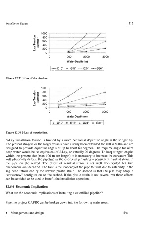
Figure 12.33 J-Lay of dry pipeline.
1000
.- 800
f 600
u,
400
gg
~ 200
0
0 1000 2000 3000
Water Depth (m)
I +- 01 0" + 01 6" + 024" 036" I
Figure 12.34 J-Lay of wet pipeline.
S-Lay installation tension is limited by a more horizontal departure angle at the stinger tip.
The present stingers on the larger vessels have already been extended for 400 to 600m and are
designed to provide departure angels of up to about 60 degrees. The required angle for ultra
deep water would be the equivalent of J-Lay, or virtually 90 degrees. To keep stinger lengths
within the present size (max 100 m arc length), it is necessary to increase the curvature This
will plastically deform the pipeline in the overbend providing a permanent residual strain in
the pipe on the seabed. The effect of residual strain is not well documented but two
phenomena are identified. The first is the tendency of the pipe to twist due to instability in the
sag bend introduced by the reverse plastic strain. The second is that the pipe may adopt a
"corkscrew" configuration on the seabed. If the plastic strain is not severe then these effects
can be avoided or be used to benefit the installation operation.
12.6.6 Economic Implication
What are the economic implications of installing a waterfilled pipeline?
Pipeline project CAPEX can be broken down into the following main areas:
0 Management and design 5%