
Page 461 - Pipelines and Risers
P. 461
428 Chapter 22
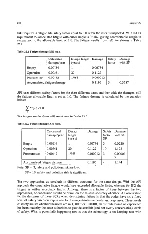
IS0 requires a fatigue life safety factor equal to 3.0 when the riser is inspected. With ISO’s
requirement the associated fatigue with our example is 0.3587, giving a comfortable margin in
comparison to the allowable limit of 1.0. The fatigue results from IS0 are shown in Table
22.1.
c
Table 22.1 Fatigue damage IS0 code.
I factor I withSF I
(years) I
Safety Damage
Design length Damage
Calculated
damage/ year
0.00734 -
Empty
0.00734
1
Operation
0.00561
0.000012 -
11365
I Pressure test I 0.00442 20 0.1122 - -
I Accumulated fatigue damage 0.1196 3 0.3587
API uses different safety factors for the three different states and then adds the damages, still
the fatigue allowable limit is set at 1.0. The fatigue damage is calculated be the equation
below:
The fatigue results from API are shown in Table 22.2.
Table 22.2 Fatigue damage API code.
Calculated Design Damage Safety Damage
damage/year length factor with SF
(Years) SF
Empty 0.00734 1 0.00734 3 0.0220
Operation 0.00561 20 0.1122 10 1.122
Pressure test 0.00442 11365 0.000012 3 O.ooOo3
I
Accumulated fatigue damage 0.1196 - 1.144
SF = 10, safety and pollution risk is significant.
The two approaches do conclude in different outcomes for the same design. With the API
approach the cumulative fatigue would have exceeded allowable limits, whereas for IS0 the
fatigue is within acceptable limits. Although there is a factor of three between the two
approaches, no conclusion should be drawn on the relative accuracy of either. An observation
for the designers of these SCRs when determining fatigue is that the codes have set a fixed
level of safety based on experience for the uncertainties on loads and responses. These levels
of safety are set whether the risers are in 1,000 ft or lO,OOOft, an estimate based on experience
has been made by the code authorities to provide sensible (and not overly conservative) levels
of safety. What is potentially happening now is that the technology is not keeping pace with