
Page 470 - Pipelines and Risers
P. 470
Piping Systems 437
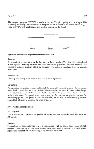
The computer program OFFPIPE is used to model the Tee piece going over the stinger. This
is done by modeling a stiffer element on the pipe, which is placed in the middle of the stinger.
From OFFPIPE both axial tension and bending moment can be found.
I I
Nml pipe Normal pipe
element Tee piece element
element
Figure 23.1 Illustration of the pipeline model used in OFFPIPE.
Sagbend
To determine the loads acting on the Tee piece in the sagbend the Tee piece element is placed
in the sagbend. Bending moment and axial tension are given the OFFPIPE analysis. The
external hydrostatic pressure acting on the empty Tee piece is calculated from the deepest
water depth.
Pressure test
The only load acting in the pressure test case is internal pressure.
Operation
For operation the design pressure subtracted the external hydrostatic pressure for minimum
water depth is used. Tie in force at the branch is taken to be maximum 15 tones and the height
of the connection point is 0.667 m above the header. The end-cap load causes the Tee-piece to
be in axial tension. For operation one case is analyzed for unrestrained pipeline and one for
restrained pipeline. The operation cases are also analyzed without the tie-in bending moment
applied to the branch to see what the effect of this is.
23.4 Finite Element Models
FE Program
The finite element analysis is performed using the commercially available program
ABAQUS.
Geometry
The analysis has been performed by a two-step approach with the global model based on shell
modeling followed by a 3-D local models built from brick elements. The local model
represented essentially the surrounding of the extruded outlet area.