
Page 32 - Piston Engine-Based Power Plants
P. 32
24 Piston Engine-Based Power Plants
This is the power stroke the drives the engine. The movement of the
piston away from the cylinder head is eventually arrested mechanically
and the piston begins to return once more to the top of the cylinder.
As it does the combustion gases are expelled from the cylinder. As the
piston reaches the top again, and all the gases have been expelled, the
cycle repeats with a fresh charge of fuel and air being admitted.
In order for gases to be admitted and removed from the cylinder
during this cycle there are valves fitted to the upper part of the cylinder
chamber. These are controlled mechanically via a shaft (the camshaft)
and levers (the rocker arms) that synchronise their movements to the
movement of the piston within the cylinder. One valve, or a set of
valves, is used to admit fuel and air into the cylinder while another
valve or set allows these same gases to be expelled once combustion
has taken place.
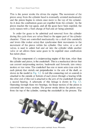
The key component of a reciprocating engine of this type, other than
the cylinder and piston, is the crankshaft. This is a mechanical device that
can convert reciprocating motion, backwards and forwards, into rotary
motion or vice versa. The crankshaft has one or more arms (one arm for
each piston) that stretch out perpendicular to the axis of the shaft, as
shown in the model in Fig. 3.2. A rod (the connecting rod or conrod) is
attached to the outside or bottom of each piston through a bearing while
the other end of this rod is attached to the arm of the crankshaft through
a second bearing. A schematic of this linkage is shown in Fig. 3.3.
Operating through these two bearings, the linear motion of the piston is
converted into rotary motion. The power stroke drives the piston away
from the top of the cylinder, turning the crankshaft in the process. The
Figure 3.2 A three-dimensional model of a piston engine crankshaft. Source: Wikimedia.