
Page 45 - Piston Engine-Based Power Plants
P. 45
Spark Ignition Engines 37
the distance between the centre of the crankshaft and the centre of the
bearing attaching the connecting rod to the crankshaft. The position
when the piston is at the top of its stroke is called top dead centre
(TDC) and the position at the bottom of the stroke is called bottom
dead centre (BDC). Since the force developed in the piston during the
power stroke is applied to the shaft through the arm as a rotational
moment, at both TDC and BDC there is no rotational moment about
the crankshaft. On the other hand, the rotational moment will be great-
est midway between TDC and BDC. The volume within the cylinder is
at its minimum when the piston is at TDC. It is at its maximum when
the piston is at BDC. The engine displacement, normally referred to as
the size of the engine, is the difference in volume between TDC and
BDC. (It is also the length of the stroke of the engine multiplied by the
cross-sectional area of the piston which is defined by its diameter, or
bore.) For a multi-cylinder engine, the volume of all the cylinders is
added together to give the total engine size.
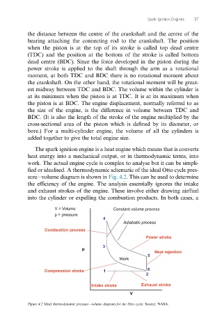
The spark ignition engine is a heat engine which means that is converts
heat energy into a mechanical output, or in thermodynamic terms, into
work. The actual engine cycle is complex to analyse but it can be simpli-
fied or idealised. A thermodynamic schematic of the ideal Otto cycle pres-
sure volume diagram is shown in Fig. 4.2. This can be used to determine
the efficiency of the engine. The analysis essentially ignores the intake
and exhaust strokes of the engine. These involve either drawing air/fuel
into the cylinder or expelling the combustion products. In both cases, a
V = Volume Constant volume process
p = pressure
4
Adiabatic process
Combustion process
Power stroke
3
p
Heat rejection
5
Work
Compression stroke 1 6
2
Intake stroke Exhaust stroke
V
Figure 4.2 Ideal thermodynamic pressure volume diagram for the Otto cycle. Source: NASA.