
Page 253 - Planning and Design of Airports
P. 253
Geometric Design of the Airfield 217
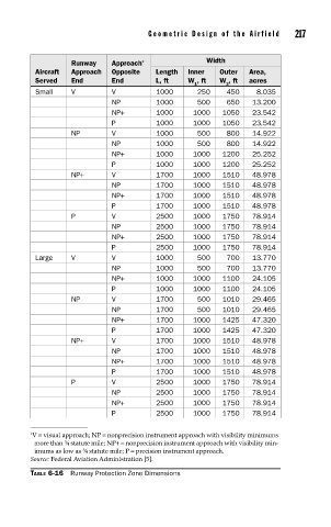
Runway Approach * Width
Aircraft Approach Opposite Length Inner Outer Area,
Served End End L, ft W , ft W , ft acres
1 2
Small V V 1000 250 450 8.035
NP 1000 500 650 13.200
NP+ 1000 1000 1050 23.542
P 1000 1000 1050 23.542
NP V 1000 500 800 14.922
NP 1000 500 800 14.922
NP+ 1000 1000 1200 25.252
P 1000 1000 1200 25.252
NP+ V 1700 1000 1510 48.978
NP 1700 1000 1510 48.978
NP+ 1700 1000 1510 48.978
P 1700 1000 1510 48.978
P V 2500 1000 1750 78.914
NP 2500 1000 1750 78.914
NP+ 2500 1000 1750 78.914
P 2500 1000 1750 78.914
Large V V 1000 500 700 13.770
NP 1000 500 700 13.770
NP+ 1000 1000 1100 24.105
P 1000 1000 1100 24.105
NP V 1700 500 1010 29.465
NP 1700 500 1010 29.465
NP+ 1700 1000 1425 47.320
P 1700 1000 1425 47.320
NP+ V 1700 1000 1510 48.978
NP 1700 1000 1510 48.978
NP+ 1700 1000 1510 48.978
P 1700 1000 1510 48.978
P V 2500 1000 1750 78.914
NP 2500 1000 1750 78.914
NP+ 2500 1000 1750 78.914
P 2500 1000 1750 78.914
∗ V = visual approach; NP = nonprecision instrument approach with visibility minimums
more than ¾ statute mile; NP+= nonprecision instrument approach with visibility min-
imums as low as ¾ statute mile; P = precision instrument approach.
Source: Federal Aviation Administration [5].
TABLE 6-16 Runway Protection Zone Dimensions