
Page 285 - Planning and Design of Airports
P. 285
246 Airp o r t D e sign
Castor angle C
90°
C of taxiway Wheelbase Radius of C R
L
L
Edge of pavement
Midpoint main
landing gear
Track-in
Safety margin S
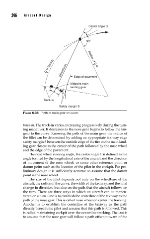
FIGURE 6-36 Path of main gear on curve.
track-in. The track-in varies, increasing progressively during the turn-
ing maneuver. It decreases as the nose gear begins to follow the tan-
gent to the curve. Knowing the path of the main gear, the radius of
the fillet can be determined by adding an appropriate taxiway edge
safety margin S between the outside edge of the tire on the main land-
ing gear closest to the center of the path followed by the nose wheel
and the edge of the pavement.
The nose wheel steering angle, the castor angle C is defined as the
angle formed by the longitudinal axis of the aircraft and the direction
of movement of the nose wheel, or some other reference point or
datum point such as the location of the pilot in the cockpit. For pre-
liminary design it is sufficiently accurate to assume that the datum
point is the nose wheel.
The size of the fillet depends not only on the wheelbase of the
aircraft, the radius of the curve, the width of the taxiway, and the total
change in direction, but also on the path that the aircraft follows on
the turn. There are three ways in which an aircraft can be maneu-
vered on a turn. One is to establish the centerline of the taxiway as the
path of the nose gear. This is called nose wheel on centerline tracking.
Another is to establish the centerline of the taxiway as the path
directly beneath the pilot and assume that this path is followed. This
is called maintaining cockpit over the centerline tracking. The last is
to assume that the nose gear will follow a path offset outward of the