Page 290 - Planning and Design of Airports
P. 290

Geometric Design of the Airfield     251


                                                                    Runway
                                                                      C L


                                                                    Taxiway
                                                                      C L


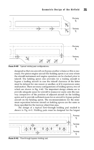
            FIGURE 6-40  Typical holding pad confi gurations.

                 designed so that one aircraft can bypass another whenever this is nec-
                 essary. For piston-engine aircraft the holding apron is an area where
                 the aircraft instrument and engine operation can be checked prior to
                 takeoff. The holding apron also provides for a trailing aircraft to
                 bypass a leading aircraft in case the takeoff clearance of the latter
                 must be delayed for one reason or another, or if it experiences some
                 malfunction. There are many configurations of holding aprons, two of
                 which are shown in Fig. 6-40. The important design criteria are to
                 provide adequate space for aircraft to maneuver easily onto the run-
                 way irrespective of the position of adjacent aircraft on the holding
                 apron and to provide sufficient room for an aircraft to bypass parked
                 aircraft on the holding apron. The recommendations for the mini-
                 mum separation between aircraft on holding aprons are the same as
                 those specified for the taxiway object-free area.
                    The design of a typical flow-through holding pad studied is
                 shown in Fig. 6-41. Holding pads must be designed for the largest


                                                                     Runway
                                                                       C L

                                                                     Taxiway
                                                                       C L

                                                                     Taxiway
                                                                       C L
            FIGURE 6-41  Flow-through bypass holding pad.
   285   286   287   288   289   290   291   292   293   294   295