
Page 291 - Planning and Design of Airports
P. 291
252 Airp o r t D e sign
aircraft which will use the pad. The holding pad should be located so
that all aircraft using the pad will be located outside both the runway
and taxiway object-free area and in a position so as not to interfere
with critical ILS signals.
Terminal Aprons and Ramps
Aircraft parking positions, also called aircraft gates or aircraft stands,
on the terminal apron or ramp are sized for the geometric properties
of a given design aircraft, including wingspan, fuselage length and
turning radii, and for the requirements for aircraft access by the vehi-
cles servicing the aircraft at the gates. Both the FAA and ICAO recom-
mend minimum clearances between any part of an aircraft and other
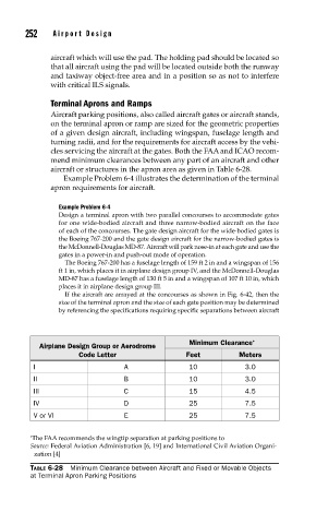
aircraft or structures in the apron area as given in Table 6-28.
Example Problem 6-4 illustrates the determination of the terminal
apron requirements for aircraft.
Example Problem 6-4
Design a terminal apron with two parallel concourses to accommodate gates
for one wide-bodied aircraft and three narrow-bodied aircraft on the face
of each of the concourses. The gate design aircraft for the wide-bodied gates is
the Boeing 767-200 and the gate design aircraft for the narrow-bodied gates is
the McDonnell-Douglas MD-87. Aircraft will park nose-in at each gate and use the
gates in a power-in and push-out mode of operation.
The Boeing 767-200 has a fuselage length of 159 ft 2 in and a wingspan of 156
ft 1 in, which places it in airplane design group IV, and the McDonnell-Douglas
MD-87 has a fuselage length of 130 ft 5 in and a wingspan of 107 ft 10 in, which
places it in airplane design group III.
If the aircraft are arrayed at the concourses as shown in Fig. 6-42, then the
size of the terminal apron and the size of each gate position may be determined
by referencing the specifications requiring specific separations between aircraft
Minimum Clearance *
Airplane Design Group or Aerodrome
Code Letter Feet Meters
I A 10 3.0
II B 10 3.0
III C 15 4.5
IV D 25 7.5
V or VI E 25 7.5
∗ The FAA recommends the wingtip separation at parking positions to
Source: Federal Aviation Administration [6, 19] and International Civil Aviation Organi-
zation [4]
TABLE 6-28 Minimum Clearance between Aircraft and Fixed or Movable Objects
at Terminal Apron Parking Positions