
Page 286 - Planning and Design of Airports
P. 286
Geometric Design of the Airfield 247
centerline. This is called judgmental oversteering tracking. The latter
type of tracking will result in the least amount of taxiway widening
but results in greater runway occupancy time and the possibility of
pilot error in judging the turn to follow. While there is no agreement
on which procedure is desirable, usually maintaining the cockpit
over the centerline tracking is preferred.
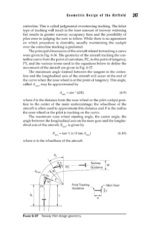
The principal dimensions of the aircraft related to tracking a curve
were given in Fig. 6-36. The geometry of the aircraft tracking the cen-
terline curve from the point of curvature, PC, to the point of tangency,
PT, and the various terms used in the equations below to define the
movement of the aircraft are given in Fig. 6-37.
The maximum angle formed between the tangent to the center-
line and the longitudinal axis of the aircraft will occur at the end of
the curve when the nose wheel is at the point of tangency. This angle,
called A , may be approximated by
max
A = sin (d/R) (6-9)
−1
max
where d is the distance from the nose wheel or the pilot cockpit posi-
tion to the center of the main undercarriage; the wheelbase of the
aircraft is often used to approximate this distance and R is the radius
the nose wheel or the pilot is tracking on the curve.
The maximum nose wheel steering angle, the castor angle, the
angle between the longitudinal axis on the nose gear and the longitu-
dinal axis of the aircraft, B , is given by
max
−1
B = tan ( w/d tan A ) (6-10)
max max
where w is the wheelbase of the aircraft.
S c
A Taxiway
W
PC Guideline
A max R
F
M
Point Tracking Main Gear
PT
Guideline
u
L
S t
d
FIGURE 6-37 Taxiway fi llet design geometry.