
Page 81 - Plant design and economics for chemical engineers
P. 81
GENERAL DESIGN CONSIDERATIONS 63
Part of-qualitative decrease (e.g., only one of two components in mix-
ture)
Reverse-opposite (e.g., backflow)
Other than-no part of the intent is achieved and something completely
different occurs (e.g., flow of wrong material)
These guide words are applied to flow, temperature, pressure, liquid level,
composition, and any other variable affecting the process.
The consequences of these deviations on the process are then assessed,
and the measures needed to detect and correct the deviations are established.
Legend:
Equipment and valves
T o FV Flow-control valve
T Tank
P P u m p
PV Pressure-control valve
RV Relief valve
V Valve
Instruments
P Pressure
T Temperature
L Level
F F l o w
I Indicator
F r o m C Controller
tank A Alarm
trucks (H High
L Low)
nH
Flammable-liquid
storage tank
T-l
1 in.
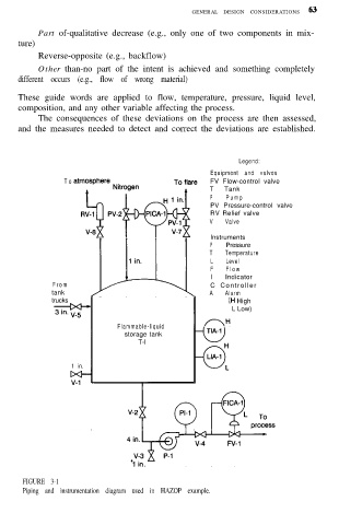
FIGURE 3-1
Piping and instrumentation diagram used in HAZOP example.